background image


Important notes 


01.04.2020 

1.2.2. 

Safety guidelines for controls 

European Directives


Directive 2006/42/EC 
Directive 2004/108/EC (EMC) 


DIN EN ISO 12100 Safety of machines – 
General principles for design 
DIN EN 60204-1 Safety of machines - 
Electrical equipment of machines, Part 1: General requirements 
DIN EN ISO 13849-1 Safety of machines - 
Safety-related parts of control systems 
ISO 13031 Earth-moving machinery - Quick couplers - Safety 

1.3. 

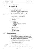
Package consists of 

The following components are included in the delivery: 


Terminal 


Joystick grips with additional parts 


Cab module 


NOX module 


Cable loom: 


Jib cable 


2x Joystick cable 


Cable for pressure reduction valve 


2x Cable for analogue pressure reduction valve 


CAN distributor 


NOX cable 


Pressure reduction valve 


USB stick with software 


USB OTG cable 


Micro USB cable 


Cable ties 


Fuse holder with 15A fuse 


RAM Mount 


Adhesive and cleaning cloth 

1.4. 

Personnel qualifications 

Unqualified personnel cannot recognise risks and are therefore exposed to a 
higher level of danger. 
Only trained personnel may be tasked with the activities described in these 
installation instructions. 
The operating company must ensure that the personnel comply with the locally 
applicable rules and regulations for safe and hazard-free work. 
The responsibility for tasks must be stipulated and made known by the operating 
company. 
These installation instructions are aimed at the following target groups: 


Kinshofer service personnel 


Certified partner's workshop personnel 


Personnel who carry out the installation and commissioning work. 


Personnel who carry out the installation and commissioning work. They are 
professionally trained and have successfully completed manufacturer's training. 

EC 

DIN EN ISO 

Service personnel 

Manufacturer 

Certified partner's 

workshop personnel 

Summary of Contents for NOXProp+

Page 1: ...Installation instructions for the control system NOXProp February 2020 EN ...

Page 2: ...es that may arise in the course of constant product development and product improvement Issuer of the original operating instructions and manufacturer of the attachment GmbH Raiffeisenstrasse 12 83607 Holzkirchen Germany Tel 49 0 8021 88 99 0 Fax 49 0 8021 88 99 37 Email info kinshofer com www kinshofer com The original operating instructions for which the manufacturer assumes responsibility are t...

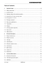
Page 3: ...of 8 1 4 Personnel qualifications 8 1 5 Type plates 9 1 6 Storage 11 1 7 Incoming goods inspection 11 1 8 Service link 11 1 9 Abbreviations 11 2 Product information 12 2 1 Proper intended use 12 2 2 Product overview 12 2 3 Terminal 13 2 4 Joystick grips 14 2 5 Pressure reduction valve 14 2 6 Cab module 15 2 7 NOX module 16 2 8 Cable loom 17 2 9 Restrictions 18 3 Technical Information 19 3 1 Genera...

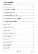
Page 4: ...ssure reduction valve without pilot valve 29 4 1 6 Connecting the excavator control system 31 4 2 Commissioning 33 4 2 1 Display controls 33 4 2 2 Functions of the buttons and rollers 34 4 2 3 Starting commissioning mode 36 4 2 4 Set joystick assignment 39 4 2 5 Adding user profiles 40 4 2 6 Selecting the tiltrotator 45 4 2 7 Carrying out automatic calibration 46 4 2 8 Setting the pressure reducti...

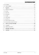
Page 5: ...0 5 1 2 Cab module 71 5 1 3 NOX module 74 5 1 4 Jib cable 76 5 1 5 CAN distributor 76 5 1 6 Joystick cable 77 5 1 7 Pressure reduction valve cable 78 5 1 8 Analogue pressure reducer valve cable 78 6 Claims warranty and liability 80 6 1 Complaint 80 6 2 Warranty and liability 80 7 Installation declaration 81 8 Locations 82 ...

Page 6: ...late on the delivery documents on the receipt on the conformity declaration and engraved on the attachment WARNING If the delivered attachment is not properly installed operated and maintained the attachment and or carried load could fall down causing serious injuries or damage to property Installation operation and maintenance of the attachment may only be carried out by authorised trained and ex...

Page 7: ...tructions in this manual during installation and commissioning Ensure that no persons are in the vicinity of the attachment when calibrating the software 1 2 Statutory safety and accident prevention The following regulations apply European directives EC Directive 2006 42 EC EC Directive 2003 37 EC Harmonised standards used DIN EN ISO 4413 Hydraulic fluid power General rules DIN EN 474 1 Earth movi...

Page 8: ...e Micro USB cable Cable ties Fuse holder with 15A fuse RAM Mount Adhesive and cleaning cloth 1 4 Personnel qualifications Unqualified personnel cannot recognise risks and are therefore exposed to a higher level of danger Only trained personnel may be tasked with the activities described in these installation instructions The operating company must ensure that the personnel comply with the locally ...

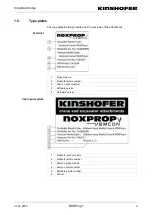
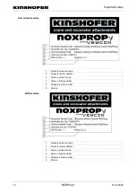
Page 9: ...e rear side of the attachment 1 Product name 2 Kinshofer article number 3 Vemcon serial number 4 Software version 5 Hardware version 1 Kinshofer product name 2 Kinshofer article number 3 Vemcon product name 4 Vemcon article number 5 Software article number 6 Version Terminal Cab input module ...

Page 10: ...inshofer article number 3 Vemcon product name 4 Vemcon article number 5 Software article number 6 Version 1 Kinshofer product name 2 Kinshofer article number 3 Vemcon product name 4 Vemcon article number 5 Software article number 6 Version Cab output module NOX module ...

Page 11: ...shipping Dispose of the packaging in accordance with regional regulations 1 8 Service link Spare parts Technical support Returns http www kinshofer com eng index php en service 1 9 Abbreviations Abbreviation Meaning AUX Auxiliary button Button for auxiliary functions CAN Controller Area Network Serial Fieldbus system with linear structure CW Clockwise CCW Counter clockwise DTM Plug connector serie...

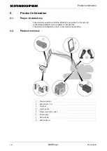
Page 12: ...ntrol the tiltrotators as well as the X Lock and conventional hydraulic quick couplers on excavators The product is intended for use in a commercial environment 2 2 Product overview 1 Plug connection 2 Boom cable 15 m 3 Terminal 4 Joystick grips 5 Pressure reduction valve 6 Cab module 7 NOX module 8 NOX cable 4 m ...

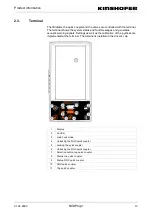
Page 13: ...ic warning signals Settings as well as the calibration of the joysticks are implemented at the terminal The terminal is installed in the driver s cab 1 Display 2 Confirm 3 Load hook mode 4 Unlocking the NOX quick coupler 5 Locking the quick coupler 6 Unlocking the NOX quick coupler 7 Selection button top quick coupler 8 Status top quick coupler 9 Status NOX quick coupler 10 NOX quick coupler 11 To...

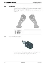
Page 14: ...igned as standard and are connected to the cab module The functions can be individually configured at the terminal for each user 1 Front button 2 Front roller 3 Rear button 4 Rear roller 2 5 Pressure reduction valve The proportional pressure reduction valve regulates the hydraulic pressure in accordance with the action that the tiltrotator should carry out The pressure reduction valve is installed...

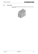
Page 15: ...Product information 01 04 2020 NOXProp 15 2 6 Cab module The cab module reads the signals from the joysticks and controls the pressure reduction valve ...

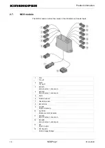
Page 16: ...2 Tilt R Tilt right 3 Extra1A Extra function 1 direction A 4 Extra1B Extra function 1 direction B 5 CAN 6 Rotation sensor 7 Absolute sensor 8 Ext B Code 9 Rot CW Rotate clockwise 10 Rot CCW Rotate counter clockwise 11 Extra2A Extra function 2 direction A 12 Extra2B Extra function 2 direction B 13 QC Quick coupler 14 QC Knuckle Quick change linkage ...

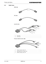
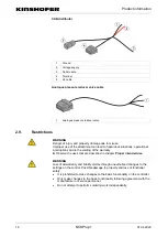
Page 17: ... 04 2020 NOXProp 17 2 8 Cable loom NOX cable Jib cable Joystick cable 1 Rear roller 2 Front roller Pressure reduction valve cable 1 Pressure reduction valve 1A 2 Analogue pressure reducer valve 3 Pressure reduction valve 1B ...

Page 18: ...perational interruptions and to the voiding of the warranty Observe the uses that are described in chapter Proper intended use WARNING Loss of all warranty and liability claims through unauthorised changes to the settings on the control Possible damage to property and loss of functional safety It is prohibited to make changes to the basic functionality on the controller Only make changes to the ba...

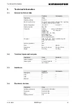
Page 19: ... M12 A coded CAN M12 D coded Ethernet 2x DTM04 12 Processor Processor ARM Cortex M7 ARM Cortex M4 ARM Cortex A53 2x ARM Cortex M0 System of protection IP67 Fuse 20 A 500 mA Dimensions 233 x 127 x 40 mm 96 x 82 x 23 mm Weight Ca 400 g Ca 500 g 3 2 Terminal inputs and outputs Description Value Number of Inputs analogue 0 to 35 V 4 Inputs digital 4 V switch threshold 35 V tolerant 4 3 3 Interfaces Te...

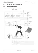
Page 20: ...operation 20 NOXProp 01 04 2020 4 Installation and initial operation 4 1 Assembly and installation 4 1 1 Electrical and hydraulic connections Hydraulic diagram 1 Cab module 2 Pressure reduction valve 3 Joystick grips 4 Terminal ...

Page 21: ...cal coupling 1 2 V 90 when coupled Because the current rating of a contact may not always be high enough 2 contacts are always used for both the battery voltage and for the ground In total the following 6 contacts are required for a sandwich system 2x Plus 2x Minus CAN_H CAN_L If additional electronics are installed in the tiltrotator and these require only small currents the attachments can share...

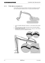
Page 22: ...vicinity of the tiltrotator where is it connected with the NOX cable 1 Screw on the NOX cable plug connection 1 on the left side of the excavator arm 2 Plug the jib cable into the plug connection and route it along the hydraulic lines and into the driver s cab 3 Fasten jib cable on the side to a hydraulic hose In doing so ensure that the jib cable does not become constricted or kinked ...

Page 23: ...in the driver s cab 1 Terminal 2 Joystick grips 3 Jib cable 4 Ground 5 Voltage supply 6 Cab module 7 Pressure reduction valve Material required included in the delivery Thread adapter Clamping ring with counter nut 2 screws Spring clip Overview Installing the joystick grips ...

Page 24: ...ether with the clamping ring and the counter nut onto the joystick base In doing so set the height such that the ergonomics are optimised for the operator 3 Secure the thread adapter with the counter nut 4 Place the joystick grip onto the thread adapter and fasten the clamping ring to the joystick grip with two screws ...

Page 25: ...op 25 5 Turn the rubber gaiter to the left and pull it over the joystick grip 6 Clamp the rubber gaiter in place with the spring clip 7 Wind the cable around the joystick as a strain relief and fasten with a cable tie or similar 8 Complete installation ...

Page 26: ... designation PS1 PS4 must likewise be connected with a suitable plug connection PS5 to the excavator control system 1 Trim the cables for buttons S3 S4 S5 S7 and S8 directly at the cable connector 2 If necessary connect the cables to the excavator control system in accordance with the allocation of the original joysticks To do so measure out the original joysticks 3 Connect the cable of roller R1 ...

Page 27: ... ground 2 Connect the red cable 2 to the ignition via the fuse 1 Screw the RAM Mount base plate onto a strut in the driver s cab 2 Alternatively clean the side window with the cleaning cloth 1 and glue the RAM Mount base plate to the side window with the adhesive 2 3 Leave the adhesive to dry for 24 hours Connecting the main distributor Mounting the terminal ...

Page 28: ...o accept proportional inputs or joysticks with the following output signals the excavator control system can be linked to the output of the cab module in order to control the pressure reduction valve via the excavator s ECU 0 5 V to 4 5 V single channel 0 5 V to 4 5 V 4 5 V to 0 5 V two channel crossed signals PWM signal 5 V voltage level 1 Plug the analogue pressure reduction valve cable into the...

Page 29: ...connected as follows 1 Plug in the pressure reduction valve cable at the cab module and connect with the pressure reduction valve 4 1 5 3 Connect the pressure reduction valve without pilot valve The pilot valve is installed in the breaker shears circuit 1 Connection A Pilot control pressure signal to the main control block 2 Connection T Tank line 3 Connection P Pilot control pressure 4 Connection...

Page 30: ...lock via the A connection 5 Connect the pressure reduction valve with the oil tank via the T connection 6 Connect the pressure reduction valve with the pump via the P connection 1 Connection A Pilot control pressure signal to the main control block 2 Connection T Tank line 3 Connection P Pilot control pressure Material required 4 mm Allen key Screw plug G1 4 1 Check which is the pressure line and ...

Page 31: ...nnecting the excavator control system The control system can exchange data with various other excavator control systems such as Leica or Trimble for example In doing so the rotation angle of the tiltrotator is transferred and displayed by the excavator control system Prerequisites Optional rotation sensor kit is installed in the tiltorator The CAN bus of the terminal is connected to the CAN bus of...

Page 32: ...ses Leica does not use the CAN Open assignment of the M12 plug but rather as follows CAN bus Leica iCON3D machine control system Allocation of 5 pole CAN M12 plug connection standard cable from Leica Geosystems AG CAN bus white and black twisted pair PIN Colour Function 1 Brown 24 V 0 75 mm 2 White CAN high 0 34 mm 3 Blue 24 V Ground 0 75 mm 4 Black CAN low 0 34 mm 5 Grey Depending on the applicat...

Page 33: ... terminal 4 2 1 Display controls The calibration of the NOX system can be carried out on the terminal display with the following controls Symbol Meaning Call up the start window Call up settings Up Left back Right forwards Down Edit Enter text in the input field Slide controller The slide controllers are used to make rough changes to the values Increase value Decrease value Closed If the button is...

Page 34: ... up centrally in a single operation The assignment for the individual information about buttons and rollers is set in the User profiles menu This menu item is part of the extended range of functions The selection of the symbols for the functions of the excavator can be set in the Joystick assignment menu The functions are shown with the following symbols Symbol Meaning Functions of the excavator c...

Page 35: ... Lock swivel linkage Unlock lock tool Vibration damping Mute radio Functions of the cabin module Rotation Toggle between rotate extra 1 Toggle between rotate extra 2 Toggle between rotate grab Toggle between rotate steer Toggle between rotate accelerator pedal Tilt Toggle between tilt grab Toggle between tilt accelerator pedal Toggle between tilt steer Toggle between tilt extra 1 Toggle between ti...

Page 36: ...xiliary circuit 2 direction B Extra 1 Extra function 1 Extra 1A Extra function 1 direction A Extra 1B Extra function 1 direction B Extra 2 Extra function 2 Extra 2A Extra function 2 direction A Extra 2B Extra function 2 direction B QC Quick coupler Steering or caterpillar control active Steering not permitted Forwards backwards in caterpillar control mode 4 2 3 Starting commissioning mode To carry...

Page 37: ...Installation and initial operation 01 04 2020 NOXProp 37 3 Tap the Settings button 4 Select the Info menu item in the main menu 5 Tap the X of NOX ...

Page 38: ...Installation and initial operation 38 NOXProp 01 04 2020 6 Tap the Enable extended functions button 7 Tap the arrow button to call up the main menu again Further menu items appear in the main menu ...

Page 39: ...f the buttons that are directly connected to the excavator control system can be set in the Joystick assignment menu 1 Select the Joystick assignment menu item in the main menu 2 Tap the Left joystick or Right joystick button 3 Tap the circle to set the function of a button 4 Select the desired function ...

Page 40: ... function 4 2 5 Adding user profiles Up to four user profiles can be added in the User profiles menu The functions of the buttons and rollers can be individually set for each user profile linked to the cab module 1 Select the User profile menu item in the main menu 2 Select the desired user profile ...

Page 41: ...the rollers need to be replaced due to damage then the rollers need to be calibrated again see Setting rollers 1 Tap the Calibrate joystick button and follow the instructions on the terminal If calibration was successful a green check appears behind each function If calibration was not successful a red cross appears for each 2 Recalibrate the joysticks if required Calibrating joysticks ...

Page 42: ...tons and rollers for the user profile proceed as follows 1 Tap the Left joy or Right joy button 2 In order to change the function of a button or roller tap the corresponding symbol 3 Select the desired function The button or roller will be assigned the selected function Setting joystick assignment ...

Page 43: ...low deflection Kinshofer recommends 50 Dead zone Describes the play around the centre position where the function is not activated Sensitivity Adjusts the maximum output signal The output signal may be reduced for training purposes Kinshofer recommends 100 for normal operation Invert Changes the direction of the roller 1 In order to change the function of a roller tap the symbol 2 Tap the Configur...

Page 44: ...ase the value and if the function activates too late lower the value 5 Adjust the Sensitivity value as required 6 To change the direction of the rollers activate the Invert check box 7 Tap the Calibrate button and follow the instructions on the terminal If calibration was successful a green check appears behind each function If calibration was not successful a red cross appears for each 8 Recalibr...

Page 45: ...g the tiltrotator All available NOX models are stored with standard values in the NOX models menu The model used can be selected and individually configured 1 Select the NOX model menu item in the main menu 2 Select NOX model used 3 Enter the serial number of the NOX model ...

Page 46: ...RNING Risk of serious injuries through unexpected tilting or rotating of the tiltrotator Only allow correspondingly trained personnel to adjust the duty cycle 1 Tap the Tilt Rotate Extra 1 Extra 2 and NOO buttons 2 In each case adapt the minimum and maximum duty cycle 3 Tap the Select model button and select the NOX model anew to reset the settings to the standard values 4 2 7 Carrying out automat...

Page 47: ... Auto calib menu item in the main menu 3 Select the tiltrotator used 4 Tap the Start auto calibration button and follow the instructions on the terminal 5 If the tiltrotator does not have a rotation sensor set the valve currents in the NOX model and Feeder menus manually ...

Page 48: ...pending on the functions WARNING Serious injuries through tiltrotator movements Ensure that there are no persons in the vicinity of the tiltrotator Calibrate the pressure reduction valve only whilst the tiltrotator is under constant observation 4 2 8 1 Select feeder type So that the feeder values for the various functions can be set the feeder type must first be selected The following types can be...

Page 49: ...rop 49 1 Select the Feeder menu item in the main menu 2 Select single or double feeder type 3 Set the minimum and maximum currents with the slide controllers 4 In order to simulate a roller select Joy emulation The values can be set under Joy emulation ...

Page 50: ... PWM A pulse width signal is generated The duty cycle can be set Typical values are as follows Minimum 10 neutral 50 and maximum 90 The PWM frequency can be used e g Volvo 481 Hz and CAT 500 Hz CAT A pulse width signal with 500 Hz is generated In addition every few minutes the output is switched to full scale deflection for a short period of time in order to outwit the self calibration of the CAT ...

Page 51: ... 2 Set the feeder values The feeder values for the various functions must be manually matched to one another if the tiltrotator has no rotation sensor option If a rotation sensor system is fitted the feeder values can be calibrated automatically see Carrying out automatic calibration To enable the feeder values to be set the valve current for the rotate function must first be adapted Adapt valve c...

Page 52: ... CW and counter clockwise rotation min CCW to 3000 mA The feeder values for the various functions are set and corrected with the help of a characteristic curve Initially the feeder value for the first point of the characteristic curve is set Once this value has been set the valve current must be reset for the rotate function before the other points can be set Correct feeder values ...

Page 53: ...Installation and initial operation 01 04 2020 NOXProp 53 1 Select the Feeder menu item in the main menu 2 Tap the Feeder correct button 3 Mark the lowest point in the chart ...

Page 54: ...Installation and initial operation 54 NOXProp 01 04 2020 4 Increase the oil flow to 3 5 Increase the valve current until the tiltrotator moves slightly 6 Tap the arrow button to call up the main menu ...

Page 55: ...OX model menu item in the main menu 8 Tap the Rotate button and set the values to the previous values 9 Alternatively set the values to the factory settings Set standard values 10 Tap the arrow button to call up the main menu 11 Select the Feeder menu item in the main menu ...

Page 56: ...OXProp 01 04 2020 12 Tap the Feeder correct button 13 Move all other points so that a characteristic curve with a positive gradient is created 14 Mark the 4th point 15 Move the roller with the rotate function until it reaches the limit stop ...

Page 57: ...attachment with a large volumetric flow and repeat steps 10 11 for one of the top points in the chart In doing so simultaneously carry out tilting rotating and extra functions 20 If there is no attachment available extrapolate the curve out to 100 as an S shaped characteristic curve If the roller is moved and in doing so there is too much or too little oil the distribution of the oil quantity for ...

Page 58: ...e operated without NOX If the direct activation is active the control system switches to direct activation automatically once the tiltrotator is uncoupled The hammer valve on the excavator is activated double acting 1 Activate direct activation 1 Select the User profile menu item in the main menu 2 Select and activate the Direct mode user profile 2 Setting the feeder values 1 Select the Feeder men...

Page 59: ...ode B feeder values 4 2 9 Adjust ramps The activation times for the pressure reduction valve and NOX at the start and end of the movement can be separately set for each function in the Ramps menu The preset standard values can generally be kept 1 Select the Ramps menu item in the main menu 2 Tap the Tilt Rotate Extra 1 Extra 2 and NOO buttons ...

Page 60: ... ensure that the pressure reduction valve is only deactivated once the NOX has completed its movement 4 2 10 Setting the quick coupler Settings for the quick coupler can be stipulated in the Quick coupler menu If the sandwich NOX system is used the top and bottom quick coupler can be set The following functions are available depending on the quick coupler used Function Explanation Oilquick If Oilq...

Page 61: ...g or locking will be provided by the breaker circuit The breaker circuit will be automatically activated as soon as the quick coupler is unlocked If the function is not desired the time is set to 0 seconds and a button assigned to the quick coupler in the user profile The button must be pressed after each unlocking and locking 1 Select the Quick coupler menu item in the main menu 2 Tap the Top or ...

Page 62: ...cavator For example a compactor requires more oil than a grab These settings can be saved in a total of 10 profiles 1 Select the Tools menu item in the main menu 2 Tap the Add button to add a tool 3 Tap the Configure button to select the tool profile and stipulate the settings 4 Enter the tool name in the input field 5 Tap the image of the tool to select the tool profile ...

Page 63: ...once pressed again Speed A Speed B Setting the oil quantity for hydraulic attachments e g speed when opening and closing the gripper NOO Inverting latchin g NOO is a freely usable output for valve coils which can control additional functions for example NOO A NOO B 4 2 12 Optional functions Some functions are optional or must be enabled Optional circuits can be set in the Machine control systems m...

Page 64: ...will be issued to you 4 3 Functional checks All functions must be tested once again at the conclusion of the commissioning Joystick functions Standard quick coupler function Function of the Kinshofer CMX Lock quick coupler WARNING Serious injuries through unexpected actions by the quick coupler and the tiltrotator Ensure that there are no persons in the vicinity of the tiltrotator 4 3 1 Joystick g...

Page 65: ...matic feeder time has been set press the button for the quick coupler on the joystick too 3 Carry out a pressure test in order to ensure that the quick coupler is properly locked 1 Press both unlock buttons on the terminal and the button for the top quick coupler simultaneously and hold for 2 seconds 2 If no automatic feeder time has been set press the button for the quick coupler on the joystick ...

Page 66: ...upler on the joystick too 3 Carry out a pressure test in order to ensure that the quick coupler is properly locked 4 4 I O status The view I O status is mainly used for troubleshooting This view displays the output currents and voltages and the input voltages 1 Select the I O Status menu item in the main menu The display of the I O Status appears Locking the top quick coupler ...

Page 67: ...correct configuration is not covered by this fault finding mechanical or hydraulic fault causes must be taken into account The following faults could arise after commissioning Fault Cause Troubleshooting No image on the terminal Fuse has blown 1 Check fuses 2 Measure electric potential between pin 1 and pin 12 The electric potential must be between 9 and 36 V Display defective 1 Order replacement ...

Page 68: ...Replace solenoid coils in the tiltrotator Tiltrotator not moving pump does not swing out Hydraulic problem 1 Check whether the armrest is closed 2 Check whether the auxiliary hydraulic system is activated 3 Check the status of the pressure reduction valve currents in the I O menu 4 Measure the voltages at the cab module during a joystick emulation 5 Replace cab module Extra function or individual ...

Page 69: ... module Machine quick coupler sensor system not working Sensor system is an option 1 Check the wiring to the sensors 2 Hold a metal part in front of the sensors to check the sensors 3 Replace NOX module Touch screen does not react At very low temperatures the touch screen can react slowly or not at all in some cases 1 Do not wear gloves 2 Remove dirt water or moisture and start anew 3 Replace term...

Page 70: ... Key DTM04 12 PC PIN Function 1 Power Supply 9 to 36 V 2 CAN2_H 3 CAN2_L 4 CAN3_H 5 CAN3_L 6 CAN4_H 7 CAN4_L 8 Analogue IN 1 1 9 Analogue IN 1 2 10 Analogue IN 2 1 11 Analogue IN 2 2 12 GND M12 D code Ethernet Female PIN Function 1 Ethernet TD 2 Ethernet RD 3 Ethernet TD 4 Ethernet RD ...

Page 71: ...p 71 M12 A code CAN Female PIN Function 1 Shield 2 Power Supply 9 to 36 V 3 GND 4 CAN1_H 5 CAN1_L 5 1 2 Cab module Key DTM04 12 PA 1 Left joystick 2 Right joystick 1 Front button 2 Front roller 3 Rear button 4 Rear roller Input ...

Page 72: ...N 8 2 Quad 4A Roller B rear 10 Analogue IN 7 2 Quad 4B Roller B front 11 Analogue IN 6 2 Quad 3B Armrest closed 12 GND Roller ground Right joystick PIN Assignment Function 1 5 V Out max 200 mA Supply for roller 2 Analogue IN 1 1 Quad 1A 3 Analogue IN 2 1 Roller A front 4 Analogue IN 3 1 Roller A rear 5 Analogue IN 4 1 Front button 6 Analogue IN 5 1 3 roller A 7 Analogue IN 5 2 3 roller B 8 Analogu...

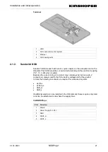
Page 73: ...alogue IN 8 2 Quad 4A QC Pin Sensor B 10 Analogue IN 7 2 Quad 4B QC Pin Sensor A 11 Analogue IN 6 2 Quad 3B QC main sensor B 12 GND Right output PIN Assignment Function 1 5 V Out max 200 mA 2 Analogue IN 1 1 Quad 1A 3 Analogue Out 1 1 Analogue pressure reducer valve 1A 4 Analogue Out 1 2 Analogue pressure reducer valve 1B 5 Out High 2 1 Pressure reduction valve 1A 6 Out High 2 2 Pressure reduction...

Page 74: ...5 1 3 NOX module 1 Tilt L 2 Tilt R 3 Extra1A 4 Extra1B 5 CAN 6 Rotation sensor 7 Absolute sensor 8 Ext B Code 9 Rot CW 10 Rot CCW 11 Extra2A 12 Extra2B 13 QC 14 QC Knuckle Valve connector Valve connector connections PIN Function 1 2 ...

Page 75: ...s PIN Function 1 V_Bat fused 2 GND 3 A 4 B Absolute sensor connections PIN Function 1 V_Bat fused 2 3 GND 4 Signal Ext B Code connections PIN Function 1 5 V 2 Analogue IN 6 1 Quad 3A 3 V_Bat fused 4 GND 5 NOOA 6 NOOB 7 NOOB 8 NOOA 9 Analogue IN 8 2 Quad 4A 10 Analogue IN 7 2 Quad 4B 11 Analogue IN 6 1 Quad 3B 12 GND ...

Page 76: ...ib cable CAN connections PIN Function 1 V_Bat 2 CAN_H 3 CAN_L 4 GND 5 1 5 CAN distributor CAN distributor 1 Ground 2 Voltage supply 3 Cab module 4 DTM plug connection terminal 5 CAN jib cable CAN connections PIN Function 1 V_Bat 2 CAN_H 3 CAN_L 4 GND ...

Page 77: ... V Out max 200 mA 5 V Out max 200 mA 2 Analogue IN 6 1 Quad 3A Analogue IN 1 1 Quad 1 A 3 FR 1 FR CH A Analogue IN 7 1 Analogue IN 2 1 4 BR 1 BR CH A Analogue IN 8 1 Analogue IN 3 1 5 Front button Analogue IN 9 1 Analogue IN 4 1 6 Analogue IN 10 1 Analogue IN 5 1 7 Analogue IN 10 2 Analogue IN 5 2 8 Rear button Analogue in 9 2 Analogue IN 4 2 9 BR 3 BR CH B Analogue IN 8 2 Quad 4A Analogue IN 3 2 ...

Page 78: ...iption Right AOM plug 1 5 V 5 V Out max 200 mA 2 Analogue IN 1 1 Quad 1A 3 AF1 1 Analogue Out 1 1 4 AF1 2 Analogue Out 1 2 5 F1A 1 Out High 2 1 6 F1B 1 Out High 2 2 7 F1B 2 Out Low 2 8 F1A 2 Out Low 2 9 Analogue IN 3 2 Quad 2A 10 Analogue IN 2 2 Quad 2B 11 Analogue IN 1 2 Quad 1B 12 AF1 3 GND GND 5 1 8 Analogue pressure reducer valve cable Analogue pressure reducer valve cable 1 Analogue pressure ...

Page 79: ...5 V Out max 200 mA 2 Analogue IN 6 1 Quad 3A 3 AF2 1 Analogue Out 3 1 4 AF2 2 Analogue Out 3 2 5 AUX1A 1 Out High 4 1 6 AUX1B 1 Out High 4 2 7 AUX1B 2 Out Low 4 8 AUX1A 2 Out Low 4 9 Analogue IN 8 2 Quad 4A 10 Analogue IN 7 2 Quad 4B 11 Analogue IN 6 2 Quad 3B 12 AF2 3 GND GND ...

Page 80: ...of the transport company delivery date and delivery time name of the driver and registration number of the transport vehicle Include the delivery papers with the return 6 2 Warranty and liability Services and deliveries are provided exclusively according to the general terms and conditions of service of the manufacturer Agreements deviating from these terms must be agreed to in writing and confirm...

Page 81: ...mplete machine is forbidden until it is confirmed that the complete system into which it is installed complies with the machinery directive The basic health and safety requirements per annex I of the machinery directive have been fulfilled The specific technical documents required per annex VII Part B have been produced and can be sent to the authorities responsible upon request This submission sh...

Page 82: ...Locations 82 NOXProp 01 04 2020 8 Locations ...

Reviews: