4
Installation and Verification
30
Keysight U7108x and U7110x Operating and Service Manual
Quick check procedure
1
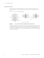
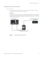
Connect the common port of the switch to Port 1 of the network analyzer and one of the outer
RF ports to Port 2 of the network analyzer as illustrated in
2
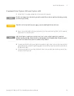
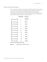
For standard drive (option 200 and option 400), apply ground to the corresponding “drive” pin
to close the selected path. Refer to
“Standard Drive (Option 200 and Option 400)”
3
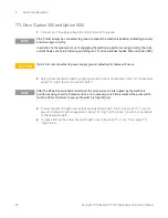
For TTL drive (option 300 and option 500), apply “High” to the corresponding “drive” pin to
close the selected path. Refer to
“TTL Drive (Option 300 and Option 500)”
4
Perform the S-parameter measurement and verify against supplemental specifications (cold
switching).
5
Repeat steps 1 to 4 until all paths are measured and verified.
Performance test
The coaxial multiport switches can be tested to the accuracy of the specifications with a network
analyzer or equivalent equipment of suitable accuracy. If a network analyzer is available, test the
instrument using the procedure in the analyzer’s operating manual.
Service instructions
Adjustment and repair
Keysight U7108x and U7110x series coaxial multiport switches do not require internal adjustments
and are not recommended for repair.
Maintenance
The connectors, particularly the connector faces, must be kept clean. For instructions on
connecting and care of your connectors, refer to the Microwave Connector Care Quick Reference
Card (08510-90360).


