


5
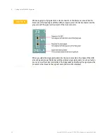
Setting up the W4641A Interposer
44
Keysight W6600A-series LPDDR4 BGA Interposers Installation Guide
Notes
:
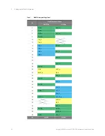
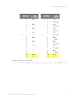
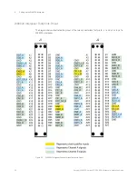
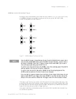
• Clock inputs for each logic analyzer pod are highlighted with yellow in this table.
• Table cells marked with
indicate logic analyzer channels that are not accessible.
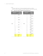
Table 2
Signals and Logic Analyzer Channels Mapping when using the W6601A Interposer
Logic Analyzer Pod
and its Channels
Signals on
U4208A probe
cable Pod A
Logic Analyzer Pod
and its Channels
Signals on
U4208A probe
cable Pod B
Pod 3
0
DQ0_B
Pod 5
0
CS0_A
1
1
2
DQ7_B
2
CA1_A
3
3
4
DMI0_B
4
CA0_A
5
5
6
DQ1_B
6
ODT_CA_A
7
7
8
DQ2_B
8
DQ7_A
9
9
10
DQ4_B
10
DMI0_A
11
11
12
DQ3_B
12
DQS0t_A
13
13
14
CS1_A
14
DQ0_A
15
15
CLK
CKE1_A
CLK
CKE0_A
CLK#
GND
CLK#
GND
Summary of Contents for LPDDR4
Page 1: ...Keysight W6600A Series LPDDR4 BGA Interposers Installation Guide ...
Page 4: ...4 Keysight W6600A series LPDDR4 BGA Interposers Installation Guide ...
Page 8: ...8 Keysight W6600A series LPDDR4 BGA Interposers Installation Guide Contents ...
Page 10: ...1 Introduction 10 Keysight W6600A series LPDDR4 BGA Interposers Installation Guide ...
Page 78: ...Index 78 Keysight W6600A series LPDDR4 BGA Interposers Installation Guide ...
Page 79: ...Keysight W6600A series LPDDR4 BGA Interposers Installation Guide 79 ...


