3-8
Keysight B1500A Configuration and Connection Guide, Edition 6
Connection Guide for Wafer Prober
SMU/GNDU connection with prober
3.1.3 MCSMU connections
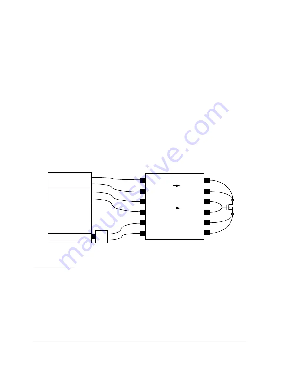
The MCSMU output connection example is shown in Figure 3-8.
For the connection of the MCSMU, the Keysight N1255A connection box is required.
Input panel provides six triaxial connectors for connecting two MCSMU and one GNDU
or SMU. Output panel provides six triaxial connectors for the High1, High2, and Low
terminals. See Figure 3-11 for image of the Input panel and the Output panel. Also see
Figure 3-8 for the connection image. And see Figure 3-10 for the internal connection. To
connect the N1255A Output terminals to the connectors as shown in Figure 3-9, use the
16494A triaxial cable.
Use the following cables to connect the N1255A to the MCSMU
•
16494A Triaxial cable, 2 ea. per one MCSMU
Use the following cables and adapter to connect the N1255A to the GNDU.
•
N1254A-100 GNDU to Kelvin adapter, 1ea.
•
16493K GNDU cable, 1ea.
•
16494A Triaxial cable, 1 ea.
Figure 3-8
N1255A Connection Example
NOTE
N1255A Input and Output terminals
If a MP/HP/HRSMU is connected instead of the GNDU, use the following cable. Also, do
not use the SMU current range less than 100 mA.
Voltage ranging of terminals is indicated near connector on the Input or Output panel.
The N1255A cannot be used for measurement of the IEC Measurement Category II, III, or
IV.
Sense
N1255A Connection Box
Force
16493L
Force
Sense
Force
Force
DUT
Sense
16494A
16494A
Sense
Force
Sense
B1500A
GNDU
MCSMU
MCSMU
Force
Sense
Force
Sense
High1
Force
Sense
High2
MCSMU1
MCSMU2
GNDU/SMU
16494A
16494A
16494A
N1254A-100
Low
Force
Sense


