


Preparing for Imaging
5
Keysight 5500 SPM User’s Guide
5-23
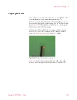
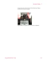
microscope base. Be sure to align the laser on the cantilever before
installing the detector in the scanner.
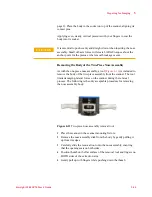
Figure 4-24
Inserting the detector module into the scanner
The Gain Switches on the detector determine whether the laser signal is
amplified before going to the rest of the electronics. Gain is disabled
when all four switches are pushed up, away from the adjustment knob.
Each switch represents one of the four quadrants in the photodetector,
therefore all switches should be either up for normal operation, or down
to increase the signal when using less reflective cantilevers.
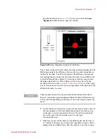
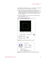
Detector alignment is completed through the PicoView software:
1
Launch PicoView. The Laser Alignment window (as well as other
windows) will open, displaying the position of the laser spot on the