


Preparing for Imaging
5
Keysight 5500 SPM User’s Guide
5-13
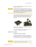
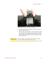
Figure 4-14
Placing scanner assembly into microscope
3
Finger-tighten the knob on the right side of the microscope base to
lock the scanner in position.
4
Attach the high voltage (red) and low voltage (blue) cables on either
side of the scanner to the sockets on the microscope base. The cables
are color coded to avoid confusion. If you are using a closed-loop
scanner, connect its third cable to the
C/L
socket on the rear of the
Head Electronics Box.
CAUTION
Be sure to withdraw tip from sample surface before disconnecting
cables and removing scanner from microscope base.