


Additional Imaging Modes
5
Keysight 5500 SPM User’s Guide
5-11
the continuity between the working electrode contact and sample to
ensure that a proper connection is achieved.
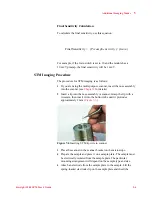
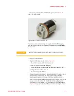
4
Place the sample plate on the microscope.
5
Plug the 3-pin EC connector of the EC/MAC cable into the 3-pin
socket on the sample plate. Plug the other end of the cable into the
EC/MAC socket on the microscope.
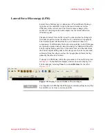
6
In PicoView, choose
Mode > CSAFM
.
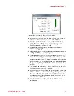
7
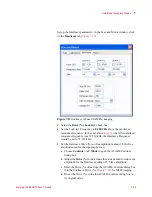
In the Servo
window enter the Bias Voltage. Typical values are
50-200 millivolts
(0.05-0.200 V).
8
Using a voltmeter, check the potential between the working electrode
contact and ground (the exposed metal of the DB44 connector on the
microscope is a good ground point). The bias should be the same as
that entered in the Servo window. If it is not, you may need to adjust
the controller calibration (see the PicoView software user guide for
additional information).
9
Enter a
Setpoint
value that is slightly more positive than the current
Deflection reading (on the HEB front panel or PicoView’s Laser
Alignment window).
10
Enter the
I
and
P
gains for the z-servo, which will dictate how
quickly the system will adjust to changes in tip deflection. A typical
starting value is
10 %
for both gains.
11
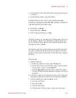
In the Realtime Images
window choose to display images for
CSAFM/Aux BNC, Deflection
and
Topography
.
12
In the Scan and Motor window’s
Scan
tab, enter:
a
Scan Speed of
1-2
ln/s.
b
Resolution of
256
.
c
Scan
Size
(in microns).
d
X Offset
and/or
Y Offset
values to set the location of the scan
center.
13
Press the
Close
switch on the HEB to raise the sample until the tip is
close to, but not touching, the sample.
NOTE
The sample plate cable can transfer low levels of vibration to the
sample. During very high resolution imaging this can affect resolution.
We recommend first plugging the sample plate cable to the 3-wire
umbilical included with the sample plate. The umbilical should then be
plugged in to the microscope base. The umbilical’s individual wires tend
to reduce the transfer of vibration.