52
Keysight M8000 Series of BER Test Solutions Installation Guide
2
Installing Modules
Removing a Module
The instructions below apply to all module types. The AXIe System Module
(ASM) has the same extraction handles and retaining screws as instrument
modules. If you should ever have to remove the ASM, follow the
instructions for instrument modules below.
1 Power down the AXIe chassis.
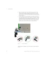
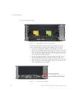
2 Fully loosen the captive retaining screws on both sides of the module.
3 For a filler panel, grasp the panel by the two captive retaining screws,
and slide it out of the chassis. For all other modules, locate the
insertion/extraction handles at each side of the module’s front panel.
Extend the plastic ends of both handles by sliding them outward on
their metal handle shafts, inwards towards each other.
4 Open the handles by pivoting them out towards you, away from the
chassis. This is easiest to do with thumb and forefinger of both hands
simultaneously. Place each thumb at the inside of the handle,
forefinger outside the handle, and rotate the handles with your
thumbs. When the handles are perpendicular with the chassis, stop.
The module should now be unseated the module from the chassis
backplane and its faceplate from the chassis front panel.
5 Grasp the levers to slide the module out of the chassis.
Synchronization Cable Configuration
This configuration requires 6 cables (provided with the M8030A), one of
them connects the M8041A SYNC OUT to the M8192A SYNC IN and rest
five connect M8192A SYNC OUT to the individual SYNC IN ports of the
M8041A and the four M8051A modules in order to synchronize the data
channels of all modules to a common system clock.
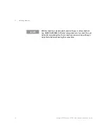
CAUTION
Ensure you fully loosened the captive module retaining screws before
trying to extract any module. If you attempt to pull the module out by the
screws (for filler panels) or by using the extraction handles (other
modules) with these screws still engaged, damage to the chassis or
module could result.

