


16
Keysight Infiniium MXR-Series Real-Time Oscilloscopes User's Guide
1
Setting Up
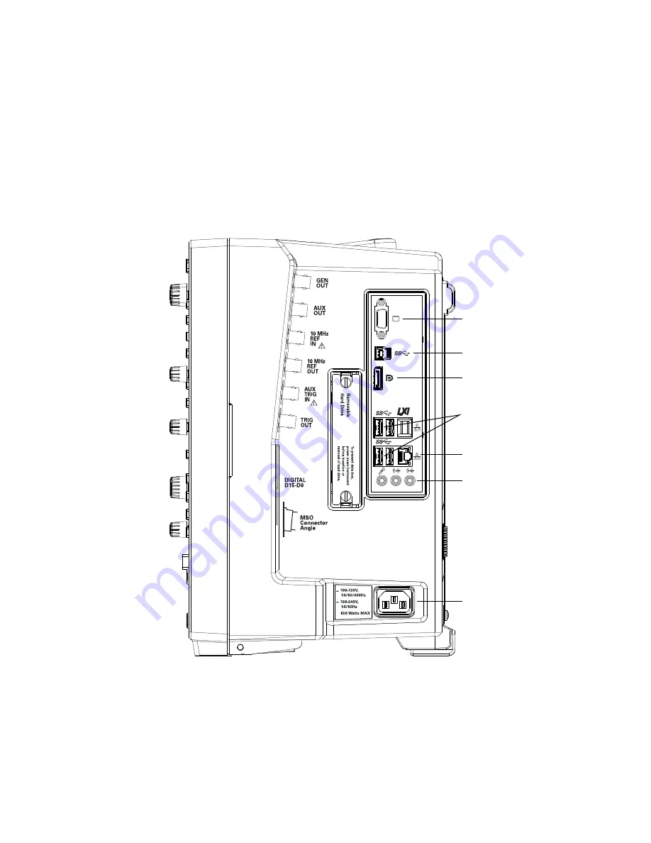
Connecting Accessories and a LAN Cable to the Oscilloscope
1
Plug the mouse and keyboard into the USB host ports. Four host ports are on
the side panel, with two more on the front panel.
2
If you want to connect to a Local Area Network, connect your LAN cable to the
RJ-45 connector on the side panel. Connect the other end to an open LAN
port.
Figure 3
Side panel
Remo
vable
Har
d Dr
iv
e
To
pr
ev
ent data loss,
po
w
er do
wn instr
u
ment
bef
o
re
inser
tion or
remo
val of har
d
dr
iv
e.
~
~
650 Watts MAX
100-240V,
50/60Hz
100-120V,
50/60/400Hz
10 MHz
REF
OUT
AUX
OUT
IG><
DJI
AUX
TRIG
IN
GEN
OUT
10 MHz
REF
IN
DIGITAL
D15-D0
MSO
Connector
Angle
External monitor
connector
Audio connectors
AC power input
Mouse and keyboard
connectors (USB 3
host ports)
LAN connector
DisplayPort
USB 3 Device port
Summary of Contents for Infiniium MXR Series
Page 1: ...Keysight Infiniium MXR Series Real Time Oscilloscopes User s Guide...
Page 10: ...10 Keysight Infiniium MXR Series Real Time Oscilloscopes User s Guide Index...
Page 20: ...20 Keysight Infiniium MXR Series Real Time Oscilloscopes User s Guide 1 Setting Up...
Page 106: ...106 Keysight Infiniium MXR Series Real Time Oscilloscopes User s Guide 6 Testing Performance...


