


51
PBJ_N-SH-e-1810.docx
20.3 Adjustment of Corner Load
Warning: Perform corner load adjustment only when corner load error is within the below-
listed amount. When corner load error is larger than this amount, replace Unit Assy (1).
Adjustable corner load error limit : models with small pan, ±15mg,
models with small pan, ±30mg, models with large pan, ±150mg,
models with large pan, ±300mg
-
Dismount ASSY, CASE (3) following “3. Inspection of the Balance Interior.
-
Adjust the level so that the bubble of level indicator comes in the red circle, and connect
the balance to power.
-
Insert CAP, PAN SUPPORTER (5) to PAN SUPPOTER ASSY(4) and Install PAN
ASSY(6).
-
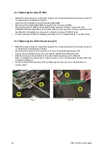
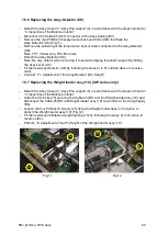
Place the calibration weight (Refer to Corner error, Table 1, Chapter 8) and press [O/T]
key to zero the display.
-
-center positions are
shown in Fig.28) and record the reading of each position.
-
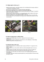
Grind slightly with the corner load adjustment tool (J4, J5) the parts of the flexures
corresponding to the off-positions of the pan showing plus errors. Note: First adjust L-R
direction as this direction is relatively less sensitive than the F-B direction. For L-R
adjustment, grind the center of the flexure part. (Fig.29) For F-B adjustment, grind the
parts of flexure just off the edge (Fig.29).
-
Repeat steps 5) and 6) and when corner load errors are reduced, place the calibration
weight at the “2”, “3”, “4” and “5” positions and further adjust until the adjustment criteria
(Refer to Table 1, Chapter 8) is met.
Fig.28
Fig.29
Summary of Contents for PBJ-N
Page 4: ...PBJ_N SH e 1810 docx 4 ...
Page 40: ...PBJ_N SH e 1810 docx 40 Fig 7 Fig 8 ...
Page 47: ...47 PBJ_N SH e 1810 docx Fig 22 Fig 23 ...
Page 55: ...55 PBJ_N SH e 1810 docx 23 Drawing Fig 31 ...
Page 56: ...PBJ_N SH e 1810 docx 56 ...
Page 57: ...57 PBJ_N SH e 1810 docx Fig 33 ...


