


PBJ_N-SH-e-1810.docx
46
Fig.20
Fig.21
-
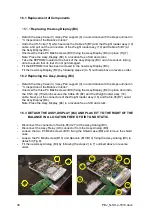
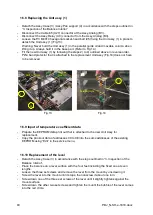
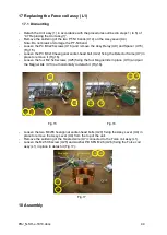
Pull the Lever fixing pin (J1) out of the lever fixing hole of the Unit assy (1). And shake the
Unit assy (1) gently. Assembly is complete if the Assy,Lever (U4) goes up and down and
hits the Lever stopper,(U12) making a clear sound in the process.
Note: If a clear sound is not heard, either the Assy,Lever (U4) pin and the Stopper
plate(U11), or the Force coil assy (L1) and the Assy,Magnet (U6), may be touching. In
both cases, adjust the positions of the respective components in accordance with
sections 6) and 11).
-
Attach the Unit assy (1) by following steps 1) to 5) of
“4.7 Replacing the Unit assy (1)” in
reverse order.
-
Fit Assy,Pan support (4) by following steps 1) to 3) of the
【
Assembly
】
procedure in “3.
Inspection of
the Balance Interior”.
-
Perform “7.2 Adjustment of Tilt Errors”.
19
Dismantling/ Assembling the Weight loader assy (10)
19.1 Dismantling
-
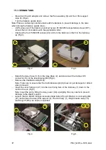
Detach the Weight loader assy (10) in accordance with steps 1) to 3) in “4.6 Replacing
the Weight loader assy (10)”.
-
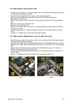
Detach the pulling spring (W7) at the Lever calibration weight support (W1).
-
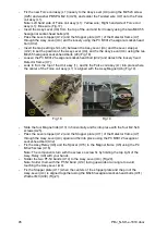
Detach the Snap ring D2 (W9), pull out the Shaft (W12), and detach the Lever calibration
weight support (W1) by pushing down the Hooking shaft (W6) hooked onto the Lever
calibration weight support (W1)(Fig.22). At this point the Nut (W14) can be loosened to
detach the Assy,Push-up stick(W28). In addition, the Pull screw for the lever (W5), the
Washer,M2 (W20), the Compression spring (W24), the Washer,M2(Small) (W11), the
Hooking shaft (W6) (bonded to the pull screw for the lever of the Detector lever (W3)) can
be detached from the Lever calibration weight support (W1).
Note: The Assy,Push-up stick(W28) and Hooking shaft (W6) etc. must not be detached
unless necessary.
-
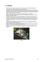
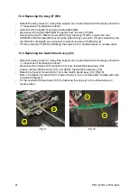
Unscrew the two M3x8 self-binding screws (W13) and the two M1.4 screws (W10) fixing
the Assy, Photo interrupter (W25). Then, remove Plate, motor case (W34). Next, undo
the clamp securing the mini-motor and Photo interrupter cables to detach the Assy,Photo
interrupter(W25) and Bottom board (W22).
-
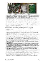
Detach the Binding spring (W17) and the Fixed ring (W27) using tweezers and split the
Drive case assy,cal wt (W15,W16) into two. Detach the mini-motor (with gear head),
Nut,clamp (W18) and Screw,clamp (W19)(Fig.23).
Note: The mini-motor gear head and Screw,clamp (W19) are coated with Pure seal
grease 2H(W26), whose viscosity barely changes with the temperature. Take care when
handling these. When re-assembling, apply a slightly generous amount of the Pure seal
grease 2H(W26) onto the gears and shaft bearing of the gear head and the thread of the
Screw,clamp (W19) (do not use any other kind of grease).
-
Remove the Snap ring D3 (W8) and detach the Detector lever (W3).
-
Detach the Detector lever shaft (W4) from the Calibration weight loading stand (W2).
Summary of Contents for PBJ-N
Page 4: ...PBJ_N SH e 1810 docx 4 ...
Page 40: ...PBJ_N SH e 1810 docx 40 Fig 7 Fig 8 ...
Page 47: ...47 PBJ_N SH e 1810 docx Fig 22 Fig 23 ...
Page 55: ...55 PBJ_N SH e 1810 docx 23 Drawing Fig 31 ...
Page 56: ...PBJ_N SH e 1810 docx 56 ...
Page 57: ...57 PBJ_N SH e 1810 docx Fig 33 ...


