background image

7-7

 BANDSCOPE 7

 Index

 Contents

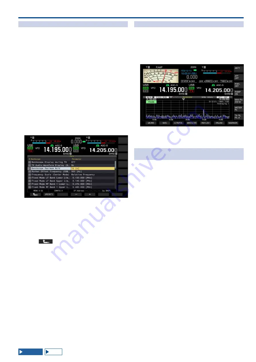
DISPLAYING THE MAXIMUM WAVEFORM VALUE

Indication of the maximum waveform value to be retained 

and displayed on the Bandscope screen enables you to 

distinguish the status of the signal.

■ Displaying the Peak Values of Waveform

1  Press [SCP] to display the bandscope on the main 

display.

2  Press [MAX.HLD] (F7) to toggle the peak value of the 

waveform between maximized and normal.

If [MAX.HLD] (F7) is unavailable in the key guide, press 

[MORE] (F1).

■ Configuring the Waveform Display Type

1  Select Group No. 8, "Bandscope", from the Menu 

screen.

2  Access Menu 02, "Bandscope Maximum Hold".
3  Press [SELECT] (F4) to allow editing of the parameter 

box.

4  Press [-] (F4) or [+] (F5) to select "10 [s]" or 

"Continuous" from the parameter box.

• 

10 [s]: Retains and displays the maximum waveform value 

of the last 10 seconds.

• 

Continuous: Retains and displays the maximum waveform 

after the bandscope has appeared.

• 

The default is "10 [s]".

5  Press 

 ] (F1).

Press [MENU] to exit.

PAUSING THE WAVEFORM DISPLAY

You can pause the waveform display on the Bandscope 

screen.
1  Press [PAUSE] (F5) to pause the displayed waveform.

• 

“PAUSE” appears while the waveform display is paused.

• 

If [PAUSE] (F6) is unavailable in the key guide, press 

[MORE] (F1).

• 

Pressing any key other than [MORE] (F1) and [MARKER] 

(F7) releases the pause of the waveform display.

AVERAGING THE WAVEFORM DISPLAY ON THE 

BANDSCOPE

If the waveform display on the bandscope is averaged, 

the waveform transition on the display becomes gradual, 

hence intermittent signals such as Morse code can easily 

be observed.
1  Press [AVE.] (F6) to change the averaging level.

• 

Each key press cycles the averaging level through "Off" (no 

averaging) > "1" (minimum) > "2" > "3" (maximum) > "Off". 

The averaging level appears on the upper right side of the 

grid.

• 

Pressing and holding [AVE.] (F6) cycles the averaging 

level in the reversed sequence.

• 

The default is "1".

• 

If [AVE.] (F6) is unavailable in the key guide, press [MORE] 

(F1).

Summary of Contents for TS-990S

Page 1: ... B62 2389 10 09 08 07 06 05 04 03 02 01 HF 50 MHz TRANSCEIVER TS 990S INSTRUCTION MANUAL 1 01 ...

Page 2: ......

Page 3: ...n manual The user could lose the authority to operate this equipment if an unauthorized change or modification is made INFORMATION TO THE DIGITAL DEVICE USER REQUIRED BY THE FCC This equipment has been tested and found to comply with the limits for a Class B digital device pursuant to Part 15 of the FCC Rules These limits are designed to provide reasonable protection against harmful interference i...

Page 4: ...on Locate the transceiver so as not to interfere with its ventilation Do not place books or other equipment on the transceiver that may impede the free movement of air Allow a minimum of 10 cm 4 inches between the rear of the transceiver and the wall or operating desk shelf Do not use the transceiver near water or sources of moisture For example avoid use near a bathtub sink swimming pool or in a ...

Page 5: ...le the transceiver power is turned OFF the LED lights orange While the transceiver power is turned ON the LED lights green M IN 2 Hold down M IN Memory then press After startup the Firmware Update screen appears and the firmware version can be viewed 3 Press to turn the transceiver power OFF Note There are two M IN keys on this transceiver one is for Memory and the other for Quick Memory To view t...

Page 6: ...this transceiver consists of a multiple number of and individual software components Title to and ownership of copyrights for each software component is reserved for JVC KENWOOD Corporation and the respective bona fide holder This product employs the software component in accordance with the End User License Agreement hereinafter referred to as the EULA stipulated by JVC KENWOOD Corporation and or...

Page 7: ...PC beyond our knowledge OPERATION OF THE OPTIONAL APPLICATIONS This manual is dedicated to describe the operation of this transceiver Refer to the help texts supplied with the ARCP 990 and ARHP 990 for details of operation of the ARCP 990 and ARHP 990 software installed onto your PC TREATMENT OFYOUR IMPORTANT DATA There is always a risk of Losing your important data by a transceiver failure occurr...

Page 8: ...r F3 Press F4 or F5 Press UP or DOWN Rotate the MULTI CH control ESC F1 F7 F RESET F CLOCK F LAN F USB DRIVE F ADV MENU UP MAIN SUB DOWN MULTI CH NOTATION FOR KEYS CONTROLS AND DISPLAYS In this manual each key control and display are described Notation Example Overview x x x CW CW R M S M Keys located on the front panel The X X X control The MULTI CH control The NB 1 M control Controls located on ...

Page 9: ...en closes Press Press VOX Press momentarily to activate the unique function of the key Press Press ESC Press to revert to the screen which was displayed prior to the current screen or to close the screen assigned for the particular task Press and hold Press and hold CW CW R Press and hold RESET Press and hold a key for the time configured in Menu 0 12 Long Press Duration of Panel Keys to activate ...

Page 10: ...NS 1 10 COM CONNECTOR 1 10 REMOTE CONNECTOR 1 10 EXT AT CONNECTOR 1 10 ACC2 CONNECTOR 1 11 MIC CONNECTOR 1 12 2 PANEL DESCRIPTION FRONT PANEL 2 1 REAR PANEL 2 9 MICROPHONE OPTION 2 10 MAIN SCREEN 2 11 SUB SCREEN 2 14 3 MENU MENU CONFIGURATIONS 3 1 OPENING THE MENU 3 1 OPENING THE SUB MENU 3 1 COMMON OPERATION IN THE MENU SCREEN 3 1 CLOSING THE MENU 3 1 MENU ITEMS 3 2 RESET MENU ITEMS 3 9 CLOCK MEN...

Page 11: ...NG THE ENTRY METHOD OF CW MESSAGES 5 22 STORING CW MESSAGES WITH text entry 5 22 PLAYING AND TRANSMITTING A CW MESSAGE 5 27 INTERRUPTING THE KEYING 5 27 DELETING CW MESSAGES 5 28 ADJUSTING THE MICROPHONE GAIN FOR FM MODE OPERATION 5 28 FM NARROW OPERATION 5 29 REDUCING THE DEFLECTIONS OF THE S Meter FOR USE IN FM MODE 5 29 FM REPEATER OPERATION 5 30 CONFIGURING THE TONE FREQUENCY 5 30 SELECTING TH...

Page 12: ...ION 9 1 SELECTING THE AUDIO SOURCE FOR TRANSMISSION BY SEND PTT 9 1 VOX VOICE OPERATED TRANSMIT 9 2 SWITCHING VOX VOICE ON OR OFF 9 2 ADJUSTING THE VOX GAIN 9 3 ADJUSTING THE VOX DELAY TIME 9 3 ADJUSTING THE ANTI VOX GAIN LEVEL 9 4 DELAYING THE AUDIO SIGNAL 9 5 TX MONITOR 9 5 ADJUSTING THE TX MONITOR LEVEL 9 5 SPEECH PROCESSOR 9 6 TRANSMIT FILTER 9 8 SELECTING A TX FILTER 9 8 CHANGING THE NUMBER O...

Page 13: ...G SCREEN IMAGES 16 12 CONFIGURING THE NETWORK 16 12 CONFIGURING THE IP NETWORK 16 12 CHECKING THE MAC ADDRESS 16 13 CONFIGURING THE NETWORK ADMINISTRATOR 16 14 CONFIGURING THE OUTPUT TO AN EXTERNAL METER 16 15 SELECTING THE OUTPUT SIGNAL OF AN EXTERNAL SPEAKER 16 17 DISPLAYING THE MAIN SCREEN CONTENTS ON AN EXTERNAL MONITOR 16 18 CONFIGURING THE RESOLUTION OF THE EXTERNAL MONITOR 16 18 CONFIGURING...

Page 14: ... THE LIST OF WARNING MESSAGES 18 6 TROUBLESHOOTING 18 7 SYMPTOMS ENCOUNTERED DURING RECEPTION AND TRANSMISSION 18 7 SYMPTOMS ENCOUNTERED IN ASSOCIATION WITH DATA COMMUNICATIONS PC AND NETWORK 18 11 SYMPTOMS ENCOUNTERED DURING RECORDING AND PLAYING 18 13 19 MISCELLANEOUS PRIME OPTIONAL ACCESSORIES 19 1 DEDICATED APPLICATIONS 19 1 PRODUCT SPECIFICATIONS 19 2 Index 19 3 ...

Page 15: ... supply power to the antenna system damaging the semiconductor circuits of the antenna CONNECTING AN AC POWER CABLE Use the supplied AC power cable to plug to an AC outlet with a protective grounding contact Ensure that the grounding lead from the AC plug has been properly connected to the ground terminal before plugging the AC plug into the outlet Likewise remove the ground connection only after ...

Page 16: ...he headphones are plugged in the audio line for the internal speaker or an optional external speaker is muted and the audio is heard through the headphones The following optional headphones can be used with this transceiver HS 5 monaural HS 6 monaural Note Headphones with a higher impedance also have a higher volume level Refer to BASIC OPERATIONS for details of configuration for the mixing balanc...

Page 17: ... USB connector EXTERNAL SPEAKERS EXT SP1 EXT SP2 8Ω The transceiver is equipped with two independent receivers In general audio from both receivers sounds from the internal speaker However connecting an external speaker allows you to separate the audio outputs On the rear panel two jacks for external speakers are available allowing you to connect two external speakers An external speaker with an i...

Page 18: ...ital cable with the TOSLINK connector If the transceiver is connected to the audio device the transceiver may not work correctly depending on the operating environment of your PC page 18 11 Turn the transceiver power and audio device OFF then connect the transceiver to the audio device If you turn the transceiver power ON while the audio signal sourced from the transceiver is being recorded by the...

Page 19: ... audio in the PC To control the transceiver via the USB connector using a PC you need to install the virtual COM port driver onto the PC To use the USB audio the driver available in your PC as standard will be used You can down load the ARUA 10 USB Audio Controller from the KENWOOD web site female TS 990S PC To RS 232C Serial Port To USB port RS 232C Straight Cable USB B Connector USB cable CONNEC...

Page 20: ...me linear amplifiers may enter TX mode when the control terminal is switched to the ground line For such a linear amplifier allocate pin number 2 in the REMOTE connector to connect to the GND terminal and pin number 4 to the control terminal of the linear amplifier TL 922 have been discontinued and is no longer available CONNECTION TO THE TL 922 TL 922 TS 990S Supplied 7 pin DIN Plug Use a self ma...

Page 21: ...as been configured for Advanced Menus 11 Linear Amplifier Control HF Band and 12 Linear Amplifier Control 50 MHz Band CONNECTION TO OTHER KENWOOD TRANSCEIVERS WITH A TNC TERMINAL The connection illustrated below allows packet cluster tuning using a TH D72A E TM D710A E or TM D700A E page 16 27 You can connect the TS 990S to a TM D710A E or RC D710 using an optional PG 5G and a commercially availab...

Page 22: ...g the internal antenna tuner through If you connect the AT 300 to the AT terminal the transmit power will be limited to 100 W Depending on the specifications for AT 300 The AT 300 has been discontinued and is no longer available TS 990S AT 300 ANT 1 connector CONNECTION TO A TNC MCP ETC For packet communications use an external TNC terminal node controller or MCP multi mode communication processor...

Page 23: ...k or to operate with KNS KENWOOD NETWORK COMMAND SYSTEM use an Ethernet cable straight type as shown in the illustration below page 15 3 page 16 12 Note Use a commercially available Ethernet cable TS 990S Internet Service Provider and Carrier Ethernet Cable Straight Type Broadband Router or Hub PC 1 Radio Control Program ARCP 990 PC 2 Radio Host Program ARHP 990 ...

Page 24: ...NNECTOR Pin No Pin Name Function Input Output 1 SPO Speaker output O 2 COM Commonly used for an internal relay I O 3 SS PTT Input Shorting the SS terminal to Ground starts transmission I 4 MKE The make terminal for an internal relay Shorts to the common terminal during transmission I O 5 BRK The break terminal for an internal relay Shorts to the common terminal during reception I O 6 ALC ALC input...

Page 25: ...elch Low impedance Tight Squelch High impedance O 6 MMET Sends the main band meter levels O 7 SSQ Sends the sub band squelch control signal 8 GND Ground 9 PKS PTT Input for data communication DATA SEND Connecting to the PTT output interface for the TNC MCP and PC connection Shorting the PKS pin to Ground starts the transmission During transmission using the PKS pin mutes the unnecessary modulation...

Page 26: ... CONNECTOR Pin No Pin Name Function Input Output 1 MIC Signal input from the microphone I 2 SS Microphone standby PTT control I 3 MD Microphone Down control I 4 MU Microphone Up control I 5 8 A Provides DC 8 V to the microphone O 6 NC No connection 7 MSG Microphone Ground 8 MCG Ground ...

Page 27: ... key AT TUNE Press to toggle the internal antenna tuner between active and inactive page 4 21 Press and hold to begin tuning the internal antenna tuner page 4 21 AT LED Lights green while the antenna tuner is active Blinks green during tuning f PHONES jack Connect a set of headphones 4 to 32Ω page 1 2 g PADDLE jack Connect a paddle for CW operation page 1 3 h USB A connector You can connect any co...

Page 28: ...he input level to the speech processor page 9 6 PROC OUT control Rotate to adjust the output level from the speech processor page 9 7 r Speech Processor key PROC SEL Press to toggle the Speech Processor between active and inactive page 9 6 Press and hold to open or close the Speech Processor screen page 9 7 Speech Processor LED Lights green while the Speech Processor is active s Power Carrier cont...

Page 29: ...ansmit using the sub band Lights green while the sub band squelch is open I RX Sub band key RX S Press to toggle reception on the sub band between active and inactive page 5 3 RX Sub band LED Lights green while the sub band is in receive mode J TX Sub band key TX S Press while in Simplex mode to switch the operating mode to Split mode Press again to reverts to Simplex mode page 5 1 Press and hold ...

Page 30: ...of 1 MHz Hold the key down to continuously increase the frequency While a configuration screen is open press to execute the key task which varies depending on the configuration screen For example press to increase or continuously increase the parameter in the proper step size page 4 14 Sub Band access key SUB Press to switch the current operating band to the sub band This key also shifts the curso...

Page 31: ...e Blanker 2 Sub band key NB2 SEL S Press to toggle the Noise Blanker 2 for the sub band between active and inactive page 6 9 Press and hold to open or close the Noise Blanker 2 Sub Band screen page 6 10 AGC OFF key for Sub band AGC OFF S Press to toggle the Automatic Gain Control AGC for the sub band between active and inactive page 5 5 AGC key for Sub band AGC SEL S Press to cycle the speed of th...

Page 32: ...o toggle the Transverter between active and inactive page 16 33 TX Drive Output key DRV Press to toggle the TX Drive Output between active and inactive page 4 21 DRV LED Lights green while the TX Drive Output is active Receive Antenna key RX ANT Press to toggle the input and output of the receive antenna between active and inactive page 4 20 page 4 21 Notch Filter Main band key NCH SEL M Press to ...

Page 33: ... sub screen page 4 4 Press and hold to switch between the standard display mode and the expanded display mode page 4 4 Quick Memory keys MR key Press to toggle the Quick Memory mode between active and inactive page 10 8 Press and hold to clear all the operating data stored in Quick Memory Channels page 10 9 M IN key Press to save data in Quick Memory Channels page 10 8 MENU key Press to open the M...

Page 34: ...tch Filter Sub band key NCH SEL S Press to toggle the Manual Notch Filter for the sub band between active and inactive page 6 10 Press and hold to toggle the Manual Notch Filter bandwidth for the sub band between normal and wide page 6 10 NCH Sub band LED Lights green while the manual notch for the sub band is active page 6 11 Automatic Notch Filter Sub band key A NCH SEL S Press to toggle the Aut...

Page 35: ...r applies I the main power source to the transceiver While the main power I O switch is in the O position you cannot start up the transceiver by pressing page 4 1 g AC IN connector This is the connector for the AC main power source input Use the supplied AC power cable to connect to a 120 V rating AC outlet K Type or a 220 240 V rating AC outlet E Type Do not use a power cable other than supplied ...

Page 36: ...nu 2 page 16 15 r REMOTE connector Mates with a linear amplifier foot switch and other external equipment Use the supplied 7 pin DIN plug to mate with page 1 6 page 1 10 s ACC 2 connector Connects to an external equipment such as an external terminal Use the supplied 13 pin DIN plug to mate with page 1 8 page 1 10 t KEY jack Connects to an electronic keyer such as a bug key or electronic keyer and...

Page 37: ... while an external antenna tuner or the internal antenna tuner for RX is active and blinks while tuning page 4 21 Appears while a transverter is active page 16 33 TX TUNE Appears and disappears alternately while TX Tuning is active page 9 13 Displays the transmit power level Disappears when the transmit signal is sent through the DRV connector page 4 17 B 30WPM Displays the keying speed When rotat...

Page 38: ...er dedicated to the sub band page 4 18 D Displays the meter dedicated to the main band The meter can be displayed as either analog or digital Two styles of analog meter can be selected page 4 19 E Displays the operating mode in use Appears in yellow while Auto Mode is active Displays the mode name and the sub number D1 D2 and D3 while in the DATA mode page 4 10 page 4 11 NOTCH Appears while Manual...

Page 39: ... of the quick memory channel numbers Q0 to Q9 page 10 8 Displays the current frequency This example displays the status during fine tuning page 4 12 G MEMONAME10 Displays the Memory Channel name page 10 8 SCAN SPDn Displays the scan speed not in FM mode page 11 2 SCANNING Appears during program scan memory scan or quick memory scan page 11 1 SCAN SLOW Appears during Program Slow Scan page 11 3 CW ...

Page 40: ...ation is wider than the display area a triangle appears C MAIN Shows the selected band either the main band or the sub band page 4 7 USB Displays the operating mode in use Appears in yellow while Auto Mode is active Displays the mode name and the sub number D1 D2 and D3 while in the DATA mode page 4 10 or Appears coupled with the frequency while either RIT or XIT is active page 5 13 M SCR Displays...

Page 41: ... the selected band either the main band or the sub band page 4 7 M SCR Appears while scrolling the memory channels page 10 4 Appears while in Memory Channel mode page 10 4 Appears while in Dual Memory Channel mode page 10 4 Appears while in Quick Memory Channel mode page 10 4 VFO Appears while in VFO mode page 10 4 00 Displays the channel number 00 to E9 while in Memory Channel mode or Memory Scro...

Page 42: ......

Page 43: ...s you to configure the internal clocks LAN LAN A menu which allows you to configure the connections to your LAN AUTO MODE AUTO MODE A menu which allows you to configure the upper and lower limit frequencies Advanced ADV An advanced menu that allows detailed advanced configurations including connections to external devices SWL SWL A key which activates and displays Short Wave Listener style horizon...

Page 44: ...ground color pattern for the sub screen dial Type 1 Type 2 Type 1 4 6 0 04 Screen Saver Pattern of the screen saver Off Type 1 Type 2 Off 16 1 0 05 Screen Saver Wait Time Wait time until the screen saver activates Preview 5 sec 5 15 30 60 min Preview 5 sec 16 2 0 06 Screen Saver Message A message embedded in the screen saver A maximum of 10 alphanumeric characters TS 990 16 2 0 07 Power on Message...

Page 45: ...ophone Refer to the programmable function key list SUB 16 7 0 30 Microphone PF 4 Key Assignment Assignment of the programmable function to PF 4 microphone Refer to the programmable function key list M V Memory 16 7 0 31 Microphone DOWN Key Assignment Assignment of the programmable function to DOWN Microphone Refer to the programmable function key list DOWN Key Microphone 16 7 0 32 Microphone UP Ke...

Page 46: ...amp for the RTTY and PSK logs Local Clock Secondary Clock Local Clock 5 60 Controls Configurations Group 3 Menu Display Configuration Range Default Reference Page Control Values 3 00 Frequency Rounding Off Multi Channel Control Rounding off of the frequency when using the Multi Channel control Off On On 4 13 3 01 SSB CW FSK PSK Mode Frequency Step Size Multi Channel Control Frequency step size of ...

Page 47: ...t and Dash Reversed Keying Reversing the Dot and Dash Keying Off On Off 5 21 5 04 Paddle Microphone Up Down Keys Paddle UP and DOWN microphone Off On Off 5 19 Weight and Timing 5 05 Automatic CW TX with Keying in SSB Mode Automatic CW transmission with keying while in SSB mode Off On Off 5 18 5 06 Carrier Frequency Offset SSB mode to CW mode Correcting the carrier frequency when changing from SSB ...

Page 48: ...Reference Page Baud Rate 7 00 Baud Rate COM Port Baud Rate for the COM connector 4800 9600 19200 38400 57600 115200 bps 9600 bps 16 10 7 01 Baud Rate USB Port Baud Rate for the USB port 4800 9600 19200 38400 57600 115200 bps 115200 bps 16 10 Data Transfer 7 02 Quick Data Transfer Quick Data Transfer Off On Off 16 26 7 03 Overwrite Location Quick Data Transfer The location where the split operation...

Page 49: ...Mode 1 8 MHz Band Lower Limit min 1 705 MHz Selecting the lower limit frequency for the 1 8 MHz Band in Fixed mode minimum 1 705 MHz 1 705 000 MHz to 1 995 000 MHz in steps of 0 001 MHz 1 800 000 MHz 7 5 8 12 Fixed Mode 1 8 MHz Band Upper Limit max 2 0 MHz Selecting the upper limit frequency for the 1 8 MHz Band in Fixed mode maximum 2 0 MHz 1 710 000 MHz to 2 000 000 MHz in steps of 0 001 MHz 2 0...

Page 50: ...Hz Band in Fixed mode maximum 26 MHz 22 005 000 MHz to 26 000 000 MHz in steps of 0 001 MHz 24 9900 000 MHz 7 5 8 29 Fixed Mode 28 MHz Band Lower Limit min 26 MHz Selecting the upper limit frequency for the 28 MHz Band in Fixed mode minimum 26 MHz 26 000 000 MHz to 29 995 000 MHz in steps of 0 001 MHz 28 000 000 MHz 7 5 8 30 Fixed Mode 28 MHz Band Upper Limit max 30 MHz Selecting the upper limit f...

Page 51: ...steps of 15 min UTC 00 00 15 2 04 Secondary Clock Identification Letter Identification letter for the secondary clock One letter A to Z U 15 2 05 Date Display Format Display format for the date MMM DD YY DD MMM YY YY MMM DD MMM DD YY 15 2 Automatic Time Correction 1 00 Clock Correction using the NTP Server Automatic clock correction using the NTP Server Off On Off 15 4 01 NTP Server Address NTP Se...

Page 52: ... Control Off 16 31 12 Linear Amplifier Control 50 MHz Band Linear Amplifier Control for use in the 50 MHz band Off Active High Active High Relay Control Active High Relay TX Delay Ctrl Active Low Active Low TX Delay Control Off 16 32 13 Microphone Gain FM Mode Microphone gain in FM mode 1 to 100 in steps of 1 50 5 28 14 PKS Polarity Reverse Reversion of the PKS polarity Off On Off 16 29 15 TX Inhi...

Page 53: ... Page Read Configuration Data Reading the transceiver configuration data 12 2 Save Configuration Data Saving the transceiver configuration data 12 2 USB Flash Drive Formatting Formatting the USB flash drive 12 1 Safe Removal of USB Flash Drive Safe removal of a USB flash drive 12 1 ...

Page 54: ......

Page 55: ... to start up regardless of the configuration in Advanced Menu 22 HELLO is the default power on message You can change this to any text such as your desired message and your call sign page 16 1 If the transceiver or the ambient environment is too cold it may take time for the main screen or the sub screen to brighten TURNING THE TRANSCEIVER OFF The transceiver is equipped with the main I O power sw...

Page 56: ...fan during the standby state for the power supply unit is noticeable you can select On in Advanced Menu 22 not to increase the temperature of the power supply unit To make the standby state power consumption not exceed 0 5 W you can enable the Standby State Low Power Consumption or press the main power switch I O on the rear panel to the O position to shut down the electricity In this case it take...

Page 57: ...ease in the final unit the cooling fan at first starts rotating at low speed If the temperature increases further the cooling fan rotates at high speed If excessively high temperature is detected the transmit power is limited until the internal temperature cools down Note If a message notifies you of a detected high temperature do not shut down the transceiver with a press down of the main I O pow...

Page 58: ...s displays such as the standard mode display and the enhanced display MENU S DISP SEL Switching to the Standard Mode and to the Enhanced Mode 1 Press and hold S DISP SEL to switch to the standard or enhanced mode A long press displays or hides a dial on the sub display Changing the Display in each mode 1 Press and hold S DISP SEL to change the display In Normal Operation In the standard mode displ...

Page 59: ...3 Press SELECT F4 to allow editing of the parameter box 4 Press F4 or F5 to select Type 1 Type 2 or Type 3 Same as Main can be configured for Menu 01 Color Display Pattern Sub Screen allowing the sub screen to have the same background color as the main screen The default is Type 1 for Menu 0 00 and Same as Main Main for Menu 0 01 5 Press F1 6 Press MENU to exit CHANGING THE DISPLAY FONT You can se...

Page 60: ... dimmer settings below For example you can adjust the brightness to be brighter for daytime operation and darker for nighttime operation DIM SEL MULTI CH ESC 1 Press DIM SEL to switch the dimmer Can be selected from Dimmer 1 to Dimmer 4 ADJUSTING THE DIMMER LEVEL You can create four preset dimmer settings for each of the main display sub display and LEDs You can then use these preset settings to e...

Page 61: ... band and lights orange upon selection of the sub band so as to prevent fault operation ADJUSTING THE AF GAIN You can adjust the speaker volume Two independent AF controls are available for the main band and for the sub band respectively AF M MUTE M AF S MUTE S 1 Rotate the AF M or AF S control Clockwise increases the volume and counterclockwise decreases it Note Depending on the configurations fo...

Page 62: ...ilable for the main band and for the sub band respectively In normal operation you can fully rotate the RF control counterclockwise If an external noise or interference by another station is present rotate the control counterclockwise slightly to decrease the gain and listen to the received audio RF M RF S 1 Rotate the RF M or RF S control to adjust the RF gain Rotate the RF control counterclockwi...

Page 63: ...SB 14 1 USB 14 15 USB 14 20 USB 14 25 USB 18 MHz 18 to 19 18 068 USB 18 1 USB 18 11 USB 18 15 USB 18 16 USB 21 MHz 20 5 to 21 5 21 0 USB 21 1 USB 21 15 USB 21 2 USB 21 3 USB 24 MHz 24 to 25 24 89 USB 24 92 USB 24 94 USB 24 96 USB 24 98 USB 28 MHz 27 5 to 30 28 USB 28 3 USB 28 5 USB 29 FM 29 3 FM 50 MHz 50 to 54 50 USB 50 125 USB K type 50 15 USB E type 50 2 USB 51 FM 52 FM General 1 0 030 to 60 0 ...

Page 64: ...d and muting of the audio not used for transmission can be configured for each status DATA OFF DATA 1 DATA 2 and DATA 3 page 5 11 SELECTING THE OPERATING MODE The operating mode can be selected The transceiver can be operated in SSB LSB USB CW CW R FSK FSK R PSK PSK R FM and AM modes Mode keys LSB or USB Mode 1 Press LSB USB Each key press toggles the operating mode between LSB and USB modes LSB U...

Page 65: ...resh 6 Repeat steps 3 to 5 until frequency and operating data are configured for all points 7 Press OK F6 8 Press MENU to exit AUTO MODE Auto Mode is a convenient function allowing you to automatically switch to the correct operating mode according to your band plan You can preconfigure the auto mode frequency points and the corresponding operating modes This enables you to automatically switch th...

Page 66: ...e LSB mode should be selected for SSB frequencies lower than 10 1 MHz and USB mode should be selected for SSB frequencies higher than 10 1 MHz The following list shows an example of the configurations for the auto mode frequencies in the HF or 50 MHz bands Frequency Mode Preset Frequency Range 1 620 MHz AM 30 kHz freq 1 62 MHz 2 000 MHz CW 1 62 MHz freq 2 0 MHz 3 500 MHz LSB 2 0 MHz freq 3 5 MHz 3...

Page 67: ...ti Channel Control 3 Press SELECT F4 to allow editing of the parameter box 4 Press F4 or F5 to select On You can configure the frequency step size as listed below Menu 3 01 SSB CW FSK PSK mode 0 5 kHz 1 kHz 2 5 kHz 5 kHz 10 kHz Menu 3 02 FM mode and Menu 3 03 AM mode 5 kHz 6 25 kHz 10 kHz 12 5 kHz 15 kHz 20 kHz 25 kHz 30 kHz 50 kHz 100 kHz 5 Press F1 6 Press MENU to exit ROUNDING OFF THE FREQUENCY...

Page 68: ...s 05 9 kHz Step in AM Broadcast Band Multi Channel Control 3 Press SELECT F4 to allow editing of the parameter box 4 Press F4 or F5 to select On or Off Selecting Off allows you to change the receive frequency at the step frequency configured in Menu 3 03 FINE TUNING You can change the frequency step size of the Tuning control to be 1 10th of the default step size Fine Tuning enables you to precise...

Page 69: ...e 10 Hz digit 0 will not appear Entering the frequency deactivates the RIT and XIT However the respective offset frequencies cannot be released In any mode other than AM and FM mode and when Fine Tuning is disabled the 10 Hz digit will be the least digit that you can enter and in AM and FM modes 100 Hz digit is the least digit you can enter After entering a frequency while in Auto mode the operati...

Page 70: ...n Keys M V key RX M and RX S keys Can be operated only if the main band frequency is locked TX M and TX S keys Band Select Keypad M VFO F M V M S key M S key Mode keys Press and hold while in FM mode to enter to FM narrow mode FINE M and FINE S key CW T M and CW T S Q MR key QM IN key Touchscreen Tuning UP and DOWN TRACKING Can be operated only if the main band frequency is locked USING THE FREQUE...

Page 71: ...g into the microphone to adjust the level Adjust the level until the indication in the PWR meter slightly varies by the audio level 4 Release the PTT microphone or press SEND The MAIN BUSY TX LED light green or turns Off depending on the configuration for the squelch level Note For FM mode configure the microphone gain in Advanced Menu 13 Microphone Gain FM Mode page 5 28 ADJUSTING THE TX POWER Re...

Page 72: ...e 1 Press MAX Po F to open the TX Output Limit screen 2 Press F4 or F5 to highlight a line for a frequency band 3 Press F2 or F3 to select the transmit power to be controlled As shown below you can select the item to limit the transmit power Max Power Limit Transmit power limit for normal transmission Max Power Limit DATA Enables the configuration for the transmit power limit while in DATA Mode TX...

Page 73: ...ub band appears on the upper right side of the main display S meter for the sub band Note If an analog meter is connected to the METER terminal on the rear panel the signal level can be observed on both the front panel and the external meter page 16 15 COMP meter can be selected while the Speech Processor is active METER PEAK VALUE HOLD Indicates the held peak value in the digital meter 1 Select G...

Page 74: ...right of the cursor CHAR F Changes the character type Each time you press CHAR F the character type cycles through the following sequence ABC upper case abc lower case ÀÁÂ upper case àáâ lower case symbols ABC upper case Available Characters and Symbols A maximum of 5 characters Following are the available characters and symbols with English selected in Menu 9 01 If you wish to enter the Japanese ...

Page 75: ...The automatic control circuit activated when voltage is applied to pin 6 ALC of the REMOTE connector and the status of the automatic control circuit appears on the ALC meter Note Be sure that the connection for use with the drive output is in place as described above Rotate the PWR control to reduce the transmit power INTERNAL ANTENNA TUNER As explained in ANTENNA INSTALLATION AND CONNECTION you w...

Page 76: ... is applied to the internal antenna tuner 1 Press AT TUNE AT T appears on the main screen R appears while an external antenna tuner is active The preset tuning information corresponding to the current transmit frequency is applied to the internal antenna tuner If you change the transmit frequency the preset tuning information followed by the preset band will be automatically configured for the int...

Page 77: ... 1 07 Headphones Mixing Balance the received audio in the main band and the received audio in the sub band are completely separated for the left and right channels If Off has been configured for menu 1 08 Headphones Left Right Reverse the received audio in the main band will be allocated to the left channel and the received audio in the sub band will be allocated to the right channel Increasing th...

Page 78: ......

Page 79: ...r the main band to the sub band 2 Press TX S to select the sub band enabling you to transmit The TX S LED lights green and the SPLIT LED lights yellow and you can start the split operation 3 Tune the sub band frequency with a rotation of the Tuning S control to be the transmit frequency The sub screen the frequency difference between the main band and sub band appears as F Note Pressing TX M finis...

Page 80: ... appears on the main screen as the F value Note If you wish to cancel the operation when the step 1 above has completed press either of RX M TX M or CLR Also pressing TX M reverts the operating mode to simplex operation from the split operation To temporarily receive using the transmit frequency use the TF SET function page 5 2 SEARCHING WITH TF SET ENABLED FOR THE TRANSMIT FREQUENCY DURING RECEPT...

Page 81: ...enabled in either of the bands Fine Tuning for the other will also be enabled If the band is swapped or if the VFO data is recalled from a Memory Channel while in VFO mode Frequency Tracking will be disabled While Frequency Tracking is active the scan does not start SIMULTANEOUS MAIN BAND AND Sub band RECEPTION The transceiver has two independent receivers so that the transceiver can receive on th...

Page 82: ...e AGC time constants of the main band and sub band to FAST MID or SLOW F1 F7 MULTI CH ESC AGC SEL S AGC SEL M 1 Press one of mode keys to select any mode other than FM mode 2 Press AGC SEL M or AGC SEL S to select the AGC time constant Each time you press the key the selection cycles as follows FAST MID SLOW FAST CHANGING THE AGC TIME CONSTANT Time constant for the main band and sub band can be in...

Page 83: ...e copied to the other band will appear 4 Press OK F4 The AGC time constant is copied Press CANCEL F7 to finish the process without copying 5 Press ESC to exit Note Not only the time constant value but also the time constant value displayed on the AGC screen are copied DISABLING THE AGC If the received signal strength is sufficiently high and is stable you can disable the AGC In general disabling t...

Page 84: ... the low pass attenuation level of High Boost 1 Formant Pass This configuration attenuates frequency components outside the audio band thus providing legible characteristics Bass Boost 1 Low pass frequency components are emphasized This configuration is effective for audio that contains high pass frequency components Bass Boost 2 Low pass frequency components are emphasized This configuration prov...

Page 85: ...requency range of the receive DSP equalizer is widely different from the configured levels for the adjacent frequency ranges the received audio may not be attenuated as configured COPYING CUSTOMIZED EQUALIZER DATA You can edit the predetermined equalizer characteristics and copy the equalizer data to User 1 to User 3 F1 F7 RXEQ SEL USB 1 Press and hold RXEQ SEL The RX Equalizer screen appears 2 Pr...

Page 86: ...s the file 5 Press F2 or F3 and select the RX equalizer data file to be read The RX Equalizer data file can also be selected by a rotation of the MULTI CH control WRITING RX DSP EQUALIZER DATA TO A USB FLASH DRIVE You can create and save a number of different data files for customized DSP equalizer configurations from which you can select and read your preferred data Note Refer to ABOUT THE USB FL...

Page 87: ... of the RX equalizer data when it was saved the RX equalizer data saved in the USB flash drive overwrites the selected RX equalizer data PREAMP Preamp automatically switches at 21 5 MHz from a low gain type preamp to a sensitivity prioritized high gain type preamp Pressing the P AMP F key on the submenu located on the right side of the main screen toggles the preamp Each key press toggles this fun...

Page 88: ...grammed as Emergency Frequency disables the RIT XIT functions The transceiver will not access the Emergency Frequency while the transceiver is transmitting is in use with Voice Message Recording functions or a CW Message SWL MODE The Trio 9R 59 is a communication type receiver that took the world by storm in the 1960s In this mode a virtual dial pointer sliding horizontally in imitation of the rib...

Page 89: ...n the transceiver in SWL mode may differ from general definitions of meter bands In SWL mode you can operate the transceiver as follows RX Play Pressing RX PLAY displays the list of the stored audio files Scan Pressing SCAN starts a scan When the scan stops at a frequency the transceiver starts receiving signals on the frequency Referring to the memory channel list Pressing M LIST displays the mem...

Page 90: ... devices The transceiver continues transmission while the DATA PTT the PKS pin of the ACC 2 connector is connected to the GND Press a PF key to which DATA SEND is assigned to toggle between the transmit mode and receive mode Note If On is configured for DATA VOX you can automatically transmit page 9 2 6 Press ESC to exit Configuration for the transmit audio source line has been completed Keep in m...

Page 91: ... is a function that fine tunes the transmit frequency in steps of 10 Hz up to 9 999 kHz without changing the receive frequency If the FINE mode is active the XIT offset frequency is adjusted in steps of 1 Hz 1 Press XIT The XIT LED lights and the XIT offset frequency appears 2 Rotate the RIT XIT control The XIT transmit frequency can be fine tuned To clear the XIT offset frequency press CL The XIT...

Page 92: ...y observing the ALC meter MIC LSB USB 1 Select the desired band and frequency Selects the desired band and frequency 2 Press LSB USB to select LSB mode or USB mode or press FM AM FM N to select AM mode 3 Press down the PTT microphone The transceiver enters a transmit state 4 Speak into the microphone in your normal voice 5 Rotate the MIC control to adjust the microphone gain In SSB mode Microphone...

Page 93: ...s capable of full break in If you do not know whether the linear amplifier is capable of the function or if the linear amplifier does not correspond to the function operate the transceiver in semi break in mode Full Break in and Semi Break in cannot be used at the same time SEMI BREAK IN The transceiver does not revert to a receive state immediately after the key is released Instead the transceive...

Page 94: ...practice keying In CW mode that require the direct keying of the carrier a BFO beat frequency oscillator is required to convert the carrier into audible sound The difference in frequency between the BFO and carrier is audible as a beat sound The difference in frequency is called receive pitch The sidetone and receive pitch are the same in frequency You can turn the CW PITCH control to adjust the f...

Page 95: ...W Auto Tune if the CW keying speed of the station you are communication to is too slow or the signal strength of the station is weak or if there is interference If RIT is active the Auto Zero in CW Auto Tune works on the frequency shifted with RIT The range where the Auto Zero in CW Auto Tune functions varies depending on the receive conditions While the Bandscope or Waterfall screen is open Auto ...

Page 96: ...c keyer while in SSB mode the transceiver changes to CW mode automatically The transceiver automatically changes from USB to CW or from LSB to CW R When the transceiver enters CW mode from SSB mode a carrier frequency offset remains active regardless of whether Frequency Offset SSB Mode to CW Mode is disabled Therefore if you receive a CW signal from a station while you are in SSB mode and you wis...

Page 97: ...nu 04 Paddle Microphone Up Down Keys 3 Press SELECT F4 to allow editing of the parameter box 4 Press F4 or F5 to select On or Off The default is Off not paddling using a microphone Selecting On allows you to paddle using the microphone 5 Press F1 6 Press MENU to exit Note In Microphone Paddle mode the paddling response slows down compared with normal paddling ADJUSTING THE KEYING SPEED You can adj...

Page 98: ...fixed rations from 2 5 to 4 0 The default is Automatic 5 Press F1 6 Press MENU to exit Note If Automatic is selected for the weighting the following weight ratios apply KEYING SPEED WPM Weight 4 to 24 1 2 8 25 to 44 1 3 0 45 to 60 1 3 2 WEIGHT Reverse If Automatic is selected for the weighting increasing the keying speed also extends the weight ratio The Weighting ratio can be reduced according to...

Page 99: ...ted to the PADDLE and KEY jack and to the microphone paddle mode OPERATING MODES OF ELECTRONIC KEYER You can select the desired operating mode Iambic A or Iambic B of the electronic keyer Mode A If both paddles are open the paddles terminate code generation after generating a code element dot or dash The memory for dots and dashes are is in the static state Mode B If both paddles are open the tran...

Page 100: ...Text String has been selected for the entry method of CW messages you can follow the procedure below to store each CW message You can store CW messages in channel 1 through channel 8 Be sure that the transceiver is in CW mode The Bandscope screen must be closed with a press of SCP if the Bandscope screen opens F1 F7 ESC SCP SWL 1 Press CW CW R to select CW mode The Bandscope screen must be closed ...

Page 101: ...R to select CW mode The Bandscope screen must be closed with a press of SCP if the Bandscope screen opens 2 Press KEYER F2 to open the CW Message screen In any transmit mode other than CW mode KEYER F2 does not appear in the key guide Press CW CW R 3 Press and hold CH1 F2 CH2 F3 CH3 F4 CH4 F5 CH5 F2 CH6 F3 CH7 F4 or CH8 F5 to select the channel to which a CW message will be stored A message notify...

Page 102: ...nd symbols can be configured SPACE F1 Press to enter a space F2 and F3 Press to display the previous character or the next character F4 and F5 Press to move a pointer to the left or to the right BACK SPACE F Press to delete the character to the left of the cursor DEL F Press to delete the character to the right of the cursor CHAR F Press to change the character type Each time you press CHAR F the ...

Page 103: ...de 190 to ANO 190 ANO 190 to ANT ANT 90 to NO 90 NO 90 to NT NT 5 Press F1 6 Press MENU to exit CONFIGURING THE FIRST CONTEST NUMBER TEXT ENTRY ONLY If the contest number format consists of a three digit sequential number the 001 format you can configure the first contest number to start from Be sure that the transceiver is in CW mode and you can follow the procedure below The Bandscope screen mus...

Page 104: ...channel group containing a channel to decrement 1 the contest number appears for the channel number to which the contest number is stored Each time you press NEXT F7 a key guide for MORE F1 CH1 F2 CH2 F3 CH3 F4 and CH4 F5 and the key guide for MORE F1 CH5 F2 CH6 F3 CH7 F4 CH8 F5 and NEXT F6 alternately appears For the selection method of a channel group refer to step 3 of CHANGING THE ENTRY METHOD...

Page 105: ...2 F3 CH3 F4 CH4 F5 CH5 F3 CH6 F4 CH7 F5 and CH8 F6 to select the desired CW message The transceiver starts playing or transmitting To terminate the operation press STOP F5 5 Press ESC to exit Note If anything other than Off has been configured for Menu 5 13 Channel Number Count up Message the contest number increments as soon as the playback or transmission of a CW message of the selected channel ...

Page 106: ... distances in repeater modes F1 F7 FM AM FM N MENU SEND 1 TUNING THE FREQUENCY 2 Press FM AM FM N to enter FM mode 3 Press ADJ F from the Menu screen 4 Access the Advanced Menu 13 Microphone Gain FM Mode 5 Press SELECT F4 to allow editing of the parameter box 6 Press SEND or press down the PTT microphone The transceiver enters the transmit mode and the level meter appears 7 Speak into the micropho...

Page 107: ... enter FM mode 2 Press and hold FM AM FM N to enter the FM Narrow mode REDUCING THE DEFLECTIONS OF THE S Meter FOR USE IN FM MODE You can configure the sensitivity of the S meter to be used in FM mode by selecting either High allowing the S meter to function in the same manner as that for past HF transceivers or Low which reduces the S meter sensitivity by an expansion of the dynamic range Selecti...

Page 108: ...elect either main band or sub band The parameter box for the frequency FREQ Hz is activated 3 Press F2 or F3 to select TONE 4 Press F4 or F5 or rotate the MULTI CH control to select the tone frequency 5 Press ESC to exit Note If you press and hold RESET F1 the selected tone frequency reverts to the default 88 5 Hz Tone Frequency 67 0 88 5 114 8 151 4 177 3 203 5 250 3 69 3 91 5 118 8 156 7 179 9 2...

Page 109: ...ted band is dedicated for reception TX LED is unlit TONE is grayed out If the TX LED and RX LED for the sub band turn Off TONE CT and CROSS will also be grayed out USING THE SCAN TO SEARCH FOR THE TONE FREQUENCY A tone frequency scan makes it possible to detect the tone frequency contained in the receive signal in FM mode This function is convenient if you wish to know the tone frequency of a repe...

Page 110: ...eives the CTCSS tone to which the same CTCSS tone frequency as that is configured for the transceiver is superimposed A CTCSS tone frequency scan makes it possible to detect the CTCSS tone frequency contained in the receive signal If the transceiver receives the signal while the CTCSS tone frequency scan is in operation you will hear the audio of the receive signal regardless of whether the CTCSS ...

Page 111: ... 3 69 3 91 5 118 8 156 7 179 9 206 5 254 1 71 9 94 8 123 0 159 8 183 5 210 7 74 4 97 4 127 3 162 2 186 2 218 1 77 0 100 0 131 8 165 5 189 9 225 7 79 7 103 5 136 5 167 9 192 8 229 1 82 5 107 2 141 3 171 3 196 6 233 6 85 4 110 9 146 2 173 8 199 5 241 8 SELECTING THE CTCSS TONE Follow the procedure below to change the type of tone signal after selecting the main band or sub band F1 F7 FM AM FM N 1 Pr...

Page 112: ... to change the current band main band or sub band The scan pauses by pressing SCAN F7 while scanning the CTCSS tone frequency The scan resumes by pressing SCAN F7 again The scan pauses if the receive signal breaks off while scanning the CTCSS tone frequency The scan automatically restarts when the transceiver detects the receive signal 5 Press ESC to exit SELECTING THE CROSS TONE Cross Tone is a f...

Page 113: ...he left side and the status overwriting or insertion of the text string entry at the time of pressing Insert on the USB keyboard appears on the right Contents of transmission or reception The text string transmitted or received appears Press and hold CLEAR F4 to delete the text string Buffer of TX text string The text string to be transmitted appears Pressing PAUSE pauses the reception FFT scope T...

Page 114: ...on displayed in the RTTY Encode Decode screen in a USB flash drive F1 F7 FSK PSK REV ESC 1 Press FSK PSK REV to enter RTTY FSK mode 2 Press DECODER F3 to open the RTTY Encode Decode screen 3 Insert a USB flash drive into the USB A connector Use a USB flash drive which was formatted by the transceiver 4 Press SAVE F4 to store the contents of QSO A message notifying you of the completion of the data...

Page 115: ...lly be erroneously recognized as a valid character decoded and displayed The threshold level should be adjusted to reduce or eliminate this symptom If there are many erroneous detections due to noise increment the threshold level F1 F7 FSK PSK REV MULTI CH 1 Press FSK PSK REV to enter RTTY FSK mode 2 Press DECODE F3 to select either main band or sub band 3 Press THLD F5 to allow editing of the thr...

Page 116: ...0 FFT Scope Averaging RTTY Decode 3 Press SELECT F4 to allow editing of the parameter box 4 Press F4 or F5 to select the desired value from 0 to 9 in the parameter box Selecting the larger parameter will display the spectra with the noise component reduced The default is 0 5 Press F1 6 Press ESC to exit Note Use Fine Tuning if it is not easy to tune page 4 14 WATERFALL In linking with the audio FF...

Page 117: ...r the text strings using the USB keyboard The entered text string is placed and displayed in the text string buffer 5 Press F12 of the USB keyboard to send a text string The transceiver transmits the text string accumulated in the text string buffer The BUSY TX LED lights red and ENCODE appears on the status bar when the transceiver is in a transmit state Each letter in the text string buffer chan...

Page 118: ...vailable in the key guide press MORE F2 5 Press MSG F5 to allow editing of the message for the selected channel 6 Use functions keys the MULTI CH control or a USB keyboard to enter a text string SPACE F1 Press to enter one space F2 and F3 Press to display the previous or next character F4 and F5 Press to move the cursor to the left and right SAVE F6 Press to store the selected characters BACK SPAC...

Page 119: ...de 2 Press DECODER F3 to open the RTTY Encode Decode screen 3 Press MEMORY F5 to open the RTTY Message screen If MEMORY F5 is unavailable in the function key guide press MORE F1 An alternate key guide will appear 4 Press F3 or F4 or rotate the MULTI CH control to select a message to be sent automatically If F3 and F4 are unavailable in the key guide press MORE F1 5 Press AUTO TX F6 to enable the a...

Page 120: ... CH2 F4 CH3 F5 CH4 F6 and NEXT F7 and the key guide for F1 MORE F2 CH5 F3 CH6 F4 CH7 F5 CH8 F6 and NEXT F7 The transceiver enters the receive mode after the RTTY message displayed along with AUTO RX on the right side CONFIGURATION FOR RTTY ENCODING AND DECODING Enabling the UOS Unshift on Space If the received RTTY signal contains a space use this function to decode the letter next to the space fo...

Page 121: ...ct All or CR LF The default is All 5 Press F1 6 Press MENU to exit Diddle Operation This function is used to select what code is transmitted when all characters being entered by the operator or transmitted from a message memory have been transmitted in RTTY FSK mode You can select to transmit a space or a letter code alphabetical letter or no letter will be transmitted F1 F7 MENU MULTI CH 1 Select...

Page 122: ...S Selecting Off disables the Encode UOS 5 Press F1 6 Press MENU to exit SENDING THE NEWLINE CODE AT THE START AND END OF TRANSMISSION The new line code CR LF can be transmitted when the RTTY communication begins and ends The RTTY message begins and ends with a new line in the decode display of the receiving station making it easier to view the transmitted RTTY message F1 F7 MENU MULTI CH 1 Select ...

Page 123: ...nly or Time Stamp Frequency display the time and frequency The default is Time Stamp Frequency 5 Press F1 6 Press MENU to exit SELECTING THE TIMESTAMP TIME You can select whether the time configured for the Local Clock or the Secondary Clock is applied to the time displayed for the timestamp F1 F7 MENU MULTI CH 1 Select Group No 2 Decoding Encoding from the Menu screen 2 Access Menu 14 Clock RTTY ...

Page 124: ...he default is 2125 Hz 5 Press F1 6 Press MENU to exit CONFIGURING THE RTTY SHIFT WIDTH The difference in frequency between the mark signal and the space signal is called shift width You can configure the shift width for communication in RTTY mode F1 F7 MENU MULTI CH 1 Select Group No 2 Decoding Encoding from the Menu screen 2 Access Menu 06 FSK Spacing 3 Press SELECT F4 to allow editing of the par...

Page 125: ...and the space signal is shifted from the mark frequency by the shift frequency configured in Menu 2 06 FSK Spacing F1 F7 FSK PSK REV MENU MULTI CH 1 Select Group No 2 Decoding Encoding from the Menu screen 2 Access Menu 07 FSK Keying Polarity 3 Press SELECT F4 to allow editing of the parameter box 4 Press F4 or F5 to select On or Off The default is Off transmitting at the mark frequency by shortin...

Page 126: ... for PSK31 or PSK63 operation You can use a commercially available USB keyboard in combination with the transceiver for operation in PSK31 or PSK63 mode You can also use a PC and software for operation with the transceiver PRECAUTION For transmission in PSK mode adjust the drive until the ALC meter just begins to swing If you use an external device adjust the audio signal level of the external dev...

Page 127: ...iver as shown below while the PSK Encode Decode screen is open Pressing the Page Up or Page Down key on the USB keyboard scrolls the contents of transmission and reception Pressing EXTEND F7 extends the PSK Encode Decode screen vertically The analog meter if displayed on the main band changes to the digital meter If you press the key again the displayed PSK Encode Decode screen and the meter rever...

Page 128: ...o enter PSK mode 2 Press DECODER F3 to open the PSK Encode Decode screen 3 Insert a USB flash drive onto the USB A connector Use a USB flash drive which was formatted by the transceiver 4 Press SAVE F4 to store the contents of QSO A message notifying you of the completion of the data saving appears If SAVE F4 is unavailable in the function key guide press MORE F1 An alternate key guide will appear...

Page 129: ...ved may be erroneously recognized as a letter causing unnecessary text to be displayed The threshold level should be adjusted to reduce or eliminate this symptom If there are many erroneous detections due to noise increase the threshold level F1 F7 FSK PSK REV ESC MULTI CH 1 Press FSK PSK REV to enter PSK mode 2 Press DECODER F3 to open the PSK Encode Decode screen 3 Press THLD F5 to allow editing...

Page 130: ... Averaging PSK Decode 3 Press SELECT F4 to allow editing of the parameter box 4 Press F4 or F5 to select one from 0 to 9 Increasing the parameter maximizes the noise component The default is 0 5 Press F1 6 Press ESC to exit WATERFALL The Waterfall screen uses spectrum linking with the audio FFT scope and displays the transition of frequency components contained in the received audio signal VECTOR ...

Page 131: ... AFC function AFC appears on the upper right side of the PSK Encode Decode screen The frequency being corrected with the automatic frequency control appears below AFC on the screen If AFC F6 is unavailable in the function key guide press MORE F1 An alternate key guide will appear Each time you press this key the FET scope display cycles as follows Blank AFC AFC and NET Blank Note If you press and ...

Page 132: ...ting of the parameter box 4 Press F4 or F5 to select 8 Hz or 15 Hz The default is 15 Hz 5 Press F1 6 Press ESC to exit NET You can transmit by applying the frequency that was automatically tuned with the AFC function while receiving F1 F7 FSK PSK REV 1 Press FSK PSK REV to enter PSK mode 2 Press DECODER F3 to open the PSK Encode Decode screen 3 Press AFC F6 to select AFC NET AFC and NET light in t...

Page 133: ...rnate key guide will appear Note In PSK63 mode the operation is fixed to BPSK SELECTING PSK31 OR PSK63 The transceiver can operate in PSK31 and BPSK modes as well as in PSK63 which offers double the transfer rate Follow the procedure below to select one of them F1 F7 FSK PSK REV 1 Press FSK PSK REV to enter PSK mode 2 Press DECODER F3 to open the PSK Encode Decode screen 3 Press 31 63 F3 Toggles b...

Page 134: ...equentially in the TX and RX Transcript 6 Press F12 of a USB keyboard to receive Note If letters not transmitted yet remain in the text string buffer when F12 is pressed at step 6 WAIT appears on the status bar When the entire text string is transmitted the transceiver enters the receive mode and the BUSY TX LED and WAIT are unlit TEMPORARILY STORING AND TRANSMITTING THE TEXT STRING IN THE BUFFER ...

Page 135: ...S T U V W E X Y Z 0 1 2 3 4 5 6 7 8 9 a b c d e f g h i j k l m n o p q r s t u v w x y z À Á Â Ã Ä Å Æ Ç È É Ê Ë Ì Í Î Ï Ð Ñ Ò Ó Ô Õ Ö Ø Ù Ú Û Ü Ý Þ à á â ã ä å æ ç è é ê ë ì í î ï ð ñ ò ó ô õ ö ø ù ú û ü ý þ ÿ ß _ ª µ º No Space Line Break Utilizing an PSK Message Memory You can save frequently used fixed phases as PSK messages in the memory If you employ the automatic transmit and receive funct...

Page 136: ...ansmit your own text string using a USB keyboard after a PSK message is transmitted using the message memory Automatic Receive is a function to revert to the receive mode after an PSKY message has been sent Selecting the channel number that contains a PSK message to be sent automatically starts transmitting the message or the message temporarily stored in the buffer for the text string can be sent...

Page 137: ...message to be sent has been stored The PSK message will not automatically be transmitted from the channel for which automatic transmission of the PSK message is disabled The key guide for F1 through F7 are the key guide for configuration including F1 MORE F2 F3 F4 MSG F5 AUTO TX F6 and AUTO RX F7 In this case press MORE F2 so that the key guide will alternate between the key guide for F1 MORE F2 C...

Page 138: ... 1 5 kHz or 2 0 kHz The default is 1 5 kHz 5 Press F1 6 Press ESC to exit ReverseING THE PHASE CHANGE DIRECTION IN QPSK If the received PSK signal is not decoded properly switch the BFO frequency on the LSB side to that on the USB side and try decoding the signal If the BFO frequency for the received PSK signal is Reverseed the lower sideband and upper sideband frequencies are Reverseed the PSK si...

Page 139: ...ttenuates the interfering signal which has 2 to 3 MHz separation from the target frequency instead of the strong interfering signal in the adjacent frequencies F1 F7 ESC MULTI CH F P SEL 1 Select the main band 2 Press P SEL F to enable or disable the Preselector The default is OFF In the key guide P SEL F the status of attenuator is indicated on the lower line While the Preselector is active the s...

Page 140: ...bandwidth using the DSP function can help suppress the interference and reduce the noise level CHANGING THE IF FILTER BANDWIDTH CHARACTERISTICS SWITCHING THE RX FITER CONFIGURATIONS The configurations Types A B and C for the IF filters can instantly be switched according to your operating needs For example wide bandwidth characteristics can be configured for A standard bandwidth characteristics is...

Page 141: ...ter You can select the desired RX filter A B or C 4 Press ROOF F3 to enable to edit the Roof Filter 5 Subsequently press ROOF F3 to select the pass band width Each time you press ROOF F3 the selection cycles as follows Auto 270 500 2 7 k 6 k 15 k Add Auto Each long press of ROOF F3 cycles the selection in the reversed sequence Rotating the MULTI CH control can also change the pass band width The d...

Page 142: ...equently press IF F4 to select the filter shape Each time you press IF F4 the selection cycles as follows Medium Sharp Soft Medium The default is Medium 5 Press ESC to exit CONFIGURING THE BEHAVIOR OF HI SHIFT AND LO WIDTH SSB AND SSB DATA ONLY For use in SSB or SSB DATA mode you can configure the cutoff frequencies low and high frequencies or passband width and its amount of shift from the center...

Page 143: ...vary 5 Press F1 6 Press MENU to exit CHANGING THE AF FILTER TYPE Like the IF filters the passband width of audio frequencies can be selected from three types Narrow Medium and Wide F1 F7 ESC FIL SEL S MULTI CH FIL SEL M 1 Press and hold FIL SEL M or FIL SEL S to open the RX Filter screen The selected band and the mode name while receiving appear and the selected RX filter A B or C will be enabled ...

Page 144: ...le receiving appear and the selected RX filter A B or C is activated 3 Rotate either HI SHIFT or LO WIDTH control Rotating the HI SHIFT control clockwise increases the high cutoff frequency and rotating it counterclockwise decreases the high cutoff frequency Rotating the LO WIDTH control clockwise increases the low cutoff frequency and rotating it counterclockwise decreases the high cutoff frequen...

Page 145: ...cy range for use in FSK and PSK mode cannot be adjusted 5 Press ESC to exit Pressing FIL SEL M or FIL SEL S closes the RX Filter screen Mode Pass Bandwidth Hz Shift Frequency Hz Range Default Range Default CW 50 80 100 150 200 250 300 400 500 600 1000 1500 2000 2500 500 800 750 700 650 600 550 500 450 400 350 300 250 200 150 100 50 0 50 100 150 200 250 300 350 400 450 500 550 600 650 700 750 800 8...

Page 146: ...olding APF SEL M or APF SEL S closes the APF screen SHIFTING THE PASS BAND OF THE AUDIO PEAK FILTER You can avoid interference from adjacent frequencies by shifting the passband of the audio peak filter The amount of shift for the bassband width is 200 Hz from the CW pitch frequency F1 F7 CW CW R ESC APF SEL S APF SEL M MULTI CH 1 Press CW CW R to select CW mode 2 Press and hold APF SEL M or APF S...

Page 147: ...or NB2 as desired depending on the noise status Both can be enabled at the same time Note In FM mode you cannot use Noise Blanker Noise is suppressed more effectively if a larger value is configured but there may be some effect on the received signal F1 F7 ESC NB2 MULTI CH NB1 NB1 SEL NB2 SEL NB2 NB1 Activating or deactivating the Noise Blankers for the main band 1 Press NB1 or NB2 Noise Blanker 1...

Page 148: ...h weak signals or operate the transceiver while checking the status of noise NOTCH S NCH SEL M NCH SEL S NOTCH M Activating or deactivating the Manual Notch filter 1 Press NCH SEL M or NCH SEL S to enable the manual notch filter for the selected band The NCH SEL M LED or NCH SEL S LED lights green In the main screen NOTCH appears on the upper left side of the frequency display for the selected ban...

Page 149: ...re is a weak interference signal beat cancellation may be able to eliminate it more effectively Target Signal Interfering Wave F1 F7 ESC MULTI CH A NCH SEL M A NCH SEL S Activating the auto notch filter 1 Press A NCH SEL M or A NCH SEL S to enable the auto notch filter for the selected band The A NCH SEL M or A NCH SEL S LED lights green In the main screen A NOTCH will appear above the frequency d...

Page 150: ...cy if the filter type is displayed in the sub screen Press the key again to disable the band elimination filter for the selected band 2 Rotate the NOTCH M or NOTCH S control to adjust the notch filter frequency You can adjust the notch frequency to the point where the beat or interference is suppressed The letter Y indicating the notch frequency moves left and right if the filter type appears on t...

Page 151: ...e SPAC system can function during reception to extract periodic signals using the Noise Reduction 2 Note When Noise Reduction 1 in SSB FM or AM mode is supressing beat signals wanted signals may also be slightly suppressed This is a normal action of Noise Reduction 1 and not a failure If Noise Reduction 2 is active while the transceiver is in SSB mode the readability of the wanted signal may drop ...

Page 152: ...at canceller performs digital processing at the AF stage thus making it possible to suppress a number of periodic interference signals beat signals in the receive bandwidth You can use the beat canceller for SSB AM and FM modes Target Signal Interfering Wave Beat F1 F7 MENU BC M BC S Mode keys 1 Press one of the mode keys to select USB FM or AM mode 2 Press BC M or BC S to select the Beat Cancelle...

Page 153: ...While pressing down the PF key assigned as the DSP monitor the passband width can be expanded Assigning the DSP monitor to the PF key 1 Select Group No 0 Basic Configurations from the Menu screen 2 Access Menu 15 PF A Key Assignment to Menu 32 Microphone UP Key Assignment 3 Press SELECT F4 to allow editing of the parameter box 4 Press F3 or F5 to select DSP MONITOR 5 Press F1 6 Press MENU to exit ...

Page 154: ......

Page 155: ...ivalent to the four times of the red marker appears vertically The span until the next red marker appears in other words waterfall fall speed can be changed While the Waterfall is being displayed the bandscope height is reduced to one third compared to when only the bandscope is displayed Note In Center mode the waterfall display pauses if the receive frequency is changed In Fixed mode with the ob...

Page 156: ...ey guide press MORE F1 DISPLAYING THE BANDSCOPE AND ANOTHER SCREEN You can display the bandscope while the RTTY Encode Decode or PSK Encode Decode screen appears provided that the transceiver is in FSK or PSK mode or the configuration screen is displayed Press SCP to display the Bandscope screen with the scale in the vertical direction compressed to 1 3 The RF AF F2 ATT F5 or other function keys f...

Page 157: ... of the parameter box 4 Press F4 or F5 to select Off Carrier Point or the offset frequency The default is 500 Hz near the peak of the frequency spectra for the typical human vocal While the bandscope and Waterfall are displayed placing a marker near the frequency having the strongest level can easily zero in even in SSB mode The peak of the frequency spectra may vary or may not be distinguished du...

Page 158: ...e Bandscope screen with your fingertip you can change the receive frequency You can tune a new signal in the bandscope without rotating the Tuning control The main band frequency will change to the frequency touched by your fingertip if MAIN appears on the upper left side of the Bandscope screen Likewise the sub band frequency will change to the frequency touched by your fingertip if SUB appears T...

Page 159: ...IMIT FREQUENCY OR UPPER LIMIT FREQUENCY FOR CENTER MODE TO FIXED MODE The display frequency range the lower limit frequency and the upper limit frequency configured for Center mode can be applied to Fixed mode This is a convenient function to quickly apply the display area for Center mode to Fixed mode 1 Press and hold CTR FIX F3 The lower limit frequency and upper limit frequency selected for use...

Page 160: ...ed Transmit frequency Shifting the marker while the Waterfall is displayed extends the marker line to the Waterfall display area If the marker becomes static the marker length reverts to the original length after two seconds OFF RANGE MARKERS FOR FREQUENCIES BEYOND THE LOWER AND UPPER LIMITS While the frequency markers appear on the bandscope and in Fixed mode if the marked frequency goes beyond t...

Page 161: ...the maximum waveform after the bandscope has appeared The default is 10 s 5 Press F1 6 Press MENU to exit PAUSING THE WAVEFORM DISPLAY You can pause the waveform display on the Bandscope screen 1 Press PAUSE F5 to pause the displayed waveform PAUSE appears while the waveform display is paused If PAUSE F6 is unavailable in the key guide press MORE F1 Pressing any key other than MORE F1 and MARKER F...

Page 162: ...he attenuation in the reversed sequence The default is Off If ATT F5 is unavailable in the key guide press MORE F1 Note Changing of the attenuation for the bandscope does not influence the receive sensitivity DISPLAYING THE TRANSMISSION SIGNAL WAVEFORM While transmitting with the bandscope displayed in Center mode you can select whether or not to display the waveform of the transmit signal 1 Selec...

Page 163: ...tate the Tuning control to change the receive frequency until the receive signal is zeroed in Operation Example CW Mode 1 Press SCP to display the Bandscope and Waterfall 2 Press CTR FIX F3 to enter Center mode 3 Press SPAN F4 to select the displayed frequency span from 5 kHz through 20 kHz This helps to distinguish the CW signal 4 If you wish to observe the weak signal that hardly moves the point...

Page 164: ......

Page 165: ...rnate the key guide 3 Press ESC to exit CHANGING THE AUDIO SOURCE FOR THE AUDIO SCOPE You can select from the received audio for the main band and for the sub band 1 Press RF AF F2 on the Bandscope screen to open the Audio Scope screen If RF AF F2 is unavailable in the key guide for function keys press MORE F1 to alternate the key guide 2 Press M S F1 to toggle the selected band between the main b...

Page 166: ...dio scope will appear with six frequency steps in the horizontal direction With the frequency display span of 8 kHz the frequency step size will be 1 kHz and the audio scope will appear with eight frequency steps in the horizontal direction The default is 3 kHz CHANGING THE LEVEL OF THE OSCILLOSCOPE The amplitude of the waveform will change if the signal level applied to the oscilloscope is change...

Page 167: ...v 100 ms Div 300 ms Div The sweep time appears on the lower right side of the grid The default is 100 ms Div Each long press of TIME F6 cycles the sweep time in the reversed sequence PAUSING THE AUDIO SCOPE AND OSCILLOSCOPE If the waveform displayed in the Audio Scope screen is paused the paused waveform will be kept on hold until PAUSE F5 is pressed again Pausing the screen allows you to analyze ...

Page 168: ......

Page 169: ...transmit method The audio modulation source when the front panel SEND or the PTT microphone switch is pressed The audio modulation source when the PF key for which DATA SEND was configured in Menu 0 15 PF A Key Assignment to Menu 0 32 Microphone UP Key Assignment is pressed DATA SEL F1 F7 ESC MULTI CH SELECTING THE AUDIO SOURCE TRNASMISSION BY SEND PTT The audio sourced from the MIC connector on t...

Page 170: ...ables to transmit the data sourced from the connectors other than the MIC connector SWITCHING VOX VOICE ON OR OFF In SSB FM and AM modes you can automatically transmit by simply speaking into the microphone 1 Press VOX SEL to enable or disable the VOX function The VOX LED lights green while the VOX is active Note To transmit with VOX enabled the audio from a microphone is transmitted regardless of...

Page 171: ...configuration you can adjust the VOX level for the audio sourced from the MIC jack Even if the audio source is selected for Data VOX in the Modulation Source screen the parameter configured for VOX Gain cannot be applied Data VOX 1 Press and hold DATA SEL to open the VOX screen In the VOX screen a line highlights the selected audio source and a row highlights the selected configuration item 2 Pres...

Page 172: ...THE ANTI VOX GAIN LEVEL While VOX is active sound from not only the microphone but also from the speaker may cause VOX to start transmitting The transceiver will transmit if the speaker volume is set too high Adjust the anti VOX level based on the sound from the speaker and set a lower limit of audio to activate the VOX function to avoid accidental transmission Operations for the VOX function Voic...

Page 173: ...ng transmission This function is convenient when you check the effectiveness of the speech processor or TX DSP equalizer In FSK and PSK modes you can monitor FSK and PSK signals to be transmitted from the transceiver MONITOR MONI 1 Press MONI to enable or disable the transmit monitor The MONI LED lights green while the TX monitor is active ADJUSTING THE TX MONITOR LEVEL With this transceiver you c...

Page 174: ...rocessor is active Note The speech processor can function for the audio signal from the ANI terminal of the ACC 2 connector or from the USB B connector on the rear panel ADJUSTING THE SPEECH PROCESSOR INPUT LEVEL 1 Press a mode key to select SSB AM or FM mode 2 Press PROC SEL to enable or disable the Speech Processor 3 Press METER F to display the compression level meter COMP Note The METER COMP F...

Page 175: ...that the meter needle will swing more or less Note If you excessively increase the output level the transmit signal may be distorted resulting in the deterioration of the waveform Output level of the speech processor is applied to both the audio entered from a microphone and the audio source configured in the Modulation Source screen In FM mode the output level of speech processor is fixed and you...

Page 176: ...ions relating to the occupation of the bandwidth in the SSB mode F1 F7 MENU F TX FIL SELECTING A TX FILTER 1 Press a mode key to select SSB AM FM SSB DATA or FM DATA mode 2 Press TX FIL F to select a TX Filter Each time you press TX FIL F the filter cycles as follows FIL A FIL B FIL C Note If 2 is selected for Menu 6 05 TX Filter Numbers you can select FIL A or FIL B CHANGING THE NUMBER OF AVAILAB...

Page 177: ...00 Hz High Cut 2500 2600 2700 2800 2900 3000 3500 4000 Hz The default is 300 Hz for the low cut frequency and 2700 Hz for the high cut frequency 6 Press ESC or press and hold TX FIL F to exit TX DSP EQUALIZER The Digital signal processing DSP allows you to change the frequency characteristics of the transmitting audio signal This function makes it possible to correct the frequency characteristics ...

Page 178: ...oost 1 Low pass frequency components are emphasized This configuration is effective for audio that contains high pass frequency components Bass Boost 2 Low pass boost 2 Low pass frequency components are emphasized This configuration provides characteristics that further emphasize the low pass band compared with Bass Boost 1 Conventional Pseudo analog characteristics The frequency domain ranging fr...

Page 179: ...guration data In the following procedure you can edit and copy the configuration data for TX DSP equalizer 1 Press and hold TXEQ SEL to open the TX Equalizer screen 2 Press F2 or F3 or rotate the MULTI CH control to select the desired characteristics of the speech processor 3 Press ADJ F4 to open the TX Equalizer screen For the adjustment of the TX DSP equalizer refer to ADJUSTING THE TX DSP EQUAL...

Page 180: ...REV F1 F7 TXEQ SEL ESC MULTI CH USB 1 Press and hold TXEQ SEL to open the TX Equalizer screen 2 Insert a USB flash drive for which data files have been saved into the USB A connector Once the USB flash drive is distinguished the icon appears at the center top of the main screen 3 Press F2 or F3 or rotate the MULTI CH control to select the type of equalizer to which configuration data read from a U...

Page 181: ...Equalizer selected at step 3 will be overwritten with the configuration data for TX Equalizer to be read DISPLAYING THE SUBSCOPE DURING TX You can display the waveform on the subscope also displaying the band width of TX filter while transmitting in SSB FM or AM mode This enables you to observe the status of the transmitting audio 1 Select Group No 8 Bandscope from the Menu screen 2 Access Menu 01...

Page 182: ...e changed in the selected line for a frequency band 3 Press F2 or F3 to select TX Tune Power 4 Press F6 or F7 or rotate the MULTI CH control to select the transmit power The default is 10W Press and hold RESET F1 to reset the parameter for the selected item to its default 5 Press ESC or MAX Po F to exit Note Once TX tuning begins the wattage displayed inside the key guide of MAX Po F on the right ...

Page 183: ...be configured in each memory channel Operating Data Channel 00 to 99 P0 to P9 E0 to E9 RX Frequency Yes Yes Simplex Yes TX Frequency Yes Yes Receive Mode Yes Yes Simplex Yes Transmit Mode Yes Yes Operation category of this transceiver split operation or dual band reception Yes No Yes Start Frequency No Yes No End Frequency No Yes No Tone CTCSS cross tone Yes Yes Yes Tone Frequency Yes Yes Yes CTCS...

Page 184: ...Memory Channels SPLIT Split Operation DUAL RX Dual band Receive Operation SPLIT DUAL Displayed when receiving with transmit frequency during split operation TF watch NAME Displays the Memory Channel name L OUT Displays the lockout status of each Memory Channel The channels with check marks are not subject to the memory scan CONFIGURING THE OPERATING DATA TO A MEMORY CHANNEL You can configure the o...

Page 185: ...URING OPERATING DATA BY DIRECTLY ENTERING FREQUENCY You can configure frequency for Memory Channels or change existing Memory Channel operating data using the numeric and band select keypad This is useful when tuning the frequency to the station with a fixed frequency 1 8 50 CLR ENT Numeric and Band select Keypad M IN ESC F1 F7 1 Press M V to enter single band Memory Channel mode or press and hold...

Page 186: ...esponding memory channel number appears on the main screen 2 Press M V again to exit Single band Memory Channel mode The transceiver diverts to VFO mode OPERATING IN DUAL BAND MEMORY CHANNEL MODE The same Memory Channel can be diverted to the main band and sub band at the same time and the operating status such as split operation dual frequencies reception TF watch can be stored to a Memory Channe...

Page 187: ...el mode when the operating data is diverted for a band the unselected band also receives the data from the same channel number While the Quick Memory Channel is in use the number of the Quick Memory Channel cannot be configured TEMPORARILY CHANGING THE OPERATING DATA While using operating data configured in Memory Channel you can temporarily change the frequency and other operating data without ch...

Page 188: ...F2 or F3 or rotate the MULTI CH control to select the Memory Channel to configure the copied operating data 5 Press M IN F4 to exit The operating data in the Memory Channel selected in step 2 is copied to the Memory Channel selected at step 4 Press CANCEL F1 or ESC to exit without copying the operating data Note You cannot copy the operating data in typical Memory Channels and extensive Memory Cha...

Page 189: ...he operating data in one of the Memory Channels is cleared while operating Memory Channel mode the Memory Channel has no operating data but with the same channel number To clear all Memory Channels execute the Memory Channel reset page 16 4 CONFIGURING NAMES FOR MEMORY CHANNELS You can configure a name for each Memory Channel You can configure the Memory Channel name with a maximum of 10 alphanume...

Page 190: ... the operating data in the selected Quick Memory Channel Each time when the new operating data is stored individual operating data is shifted to the channel with the channel number incremented by 1 Note If the transceiver is placed in Memory Channel mode in the main band or the sub band the operating data cannot be configured in Quick Memory Channel even with a press of M IN Quick Memory If the op...

Page 191: ...emory Channels 2 Press and hold MR Quick Memory A message appears prompting you to clear all operating data configured in Quick Memory Channels 3 Press OK F4 to clear the operating data All operating data in the Quick Memory Channel is cleared and VFO mode is selected Press CANCEL F7 to close the message without clearing the operating data in the Quick Memory Channels MEMORY SHIFT QUICK MEMORY TO ...

Page 192: ......

Page 193: ...step size as that of the Tuning control for use in SSB CW FSK and PSK modes 100 Hz for use in AM mode and the same frequency step size as that of the MULTI CH control for use in FM mode The scan stops when the transceiver receives a signal during the Program Scan VFO Scan in FM mode or during the Memory Scan All Channel Scan Group Scan or the Quick Memory Scan Refer to RESUMING THE SCAN for the co...

Page 194: ...SPD7 300 ms SCAN SPD8 350 ms SCAN SPD9 400 ms Note In FM mode the scan time to retain each frequency during the Program Scan and VFO Scan is fixed to 80 ms and you cannot change the scan time However if the transceiver receives a CTCSS tone the scan time is extended to 400 ms In FM mode SCANNING appears in place of the scan speed SCAN HOLD In any mode other than FM mode changing the frequency with...

Page 195: ...acent frequency range the scan time to remain on each frequency to slow down the scan during the Program Scan If the scan slows down on the certain frequency frequency points and its adjacent frequency range you can carefully watch the traffic status Program Slow Scan is a function that extends at the preconfigured frequency frequency point and its adjacent frequency range the scan time to remain ...

Page 196: ...scanning There are two Memory Scans All Channel Scan that scans all Memory Channels to which the operating data has been stored and Group Scan that scans the selected and grouped Memory Channels STARTING THE SCAN 1 Press M V while in VFO mode to enter Single band Memory Channel mode or press and hold M V to enter Dual band Memory Channel mode 2 Press SCAN F5 to activate the Memory Scan Rotating th...

Page 197: ...el 0 00 to 09 6 60 to 69 1 10 to 19 7 70 to 79 2 20 to 29 8 80 to 99 3 30 to 39 9 90 to 99 4 40 to 49 P P0 to P9 5 50 to 59 E E0 to E9 Examples of Configurations for the All Channel Scan and the Group Scan If you place tick marks on Memory Groups 1 and 5 pressing SCAN F5 starts the Group Scan The Memory Channels in Memory Groups 1 and 5 will be scanned If you place tick marks on all Memory Groups ...

Page 198: ...during the Program Scan VFO Scan while in FM mode or during the Memory Scan or Quick Memory Scan regardless of the operating data The conditions to resume scanning after the scanning stops can be configured Time operated The scan stops for three seconds upon receipt of a signal If the reception continues even after three seconds the scan stops for the three seconds once a signal is received and co...

Page 199: ... external storage device MULTI CH ESC MENU F1 F7 USB F USB DRIVE 1 Insert a USB flash drive to the USB A connector blinks on the main screen and lights when the transceiver recognizes the USB flash drive Wait until the icon appears 2 Press USB DRIVE F on the Menu screen to open the USB screen 3 Select USB Flash Drive Formatting 4 Press SELECT F4 to start formatting A message prompting you the star...

Page 200: ...o do not shut down the main power switch I O Otherwise failure in the safe removal of the USB flash drive may cause damage to the USB flash drive the configuration data file the audio data file and malfunction of the transceiver Note An extension of the saved file is dat Data files will be saved using a file name consisting of the current date and time YYYYMMDD_HHMMSS dat Example 20130215_102030 d...

Page 201: ...figuration data reading appears 11 Press OK F4 to exit The transceiver automatically restarts PRECAUTION Do not remove the USB flash drive while the configuration data file or the audio data file is being read from the USB flash drive Also do not shut down the main power switch I O Otherwise failure in the safe removal of the USB flash drive may cause damage to the USB flash drive the configuratio...

Page 202: ...DSP Equalizer Press READ F6 in the TX Equalizer screen File names stored in a USB flash drive appear 3 Press F2 or F3 to select a file 4 Press NAME F to allow file name to be changed 5 Use the functions keys and the MULTI CH control to edit or enter a text string for the file name A maximum of 255 alphanumeric characters and symbols can be entered SPACE F1 Press to enter a space F2 and F3 Press to...

Page 203: ...to which the channel is assigned to start recording of the voice message A message prompting you to start recording the voice message appears If CH1 F2 to CH6 F7 are unavailable in the function key guide press MORE F1 4 Press REC IN F2 to select the source of the voice message to be recorded Each key press cycles the display through the following sequence MIC microphone ACC 2 ACC 2 connector USB U...

Page 204: ... character on the left side of the pointer DEL F Press to delete a character on the right side of the pointer CHAR F Press to change the character type Each time you press CHAR F the character type cycles through the following sequence ABC upper case abc lower case ÀÁÂ upper case àáâ lower case symbols ABC upper case 5 Press SAVE F6 to save the voice message name Press CANCEL F7 to discard the tex...

Page 205: ...ncreases Select Off to mute the voice message The default is 10 5 Press F1 6 Press MENU to exit TRANSMITTING A VOICE MESSAGE You can transmit the recorded voice message while playing ESC F1 F7 1 Press a mode key to select SSB FM or AM mode 2 Press TX MSG F2 to open the Voice Message screen 3 Press the function key CH1 F2 to CH6 F7 to be recorded to which the voice message channel number is assigne...

Page 206: ...with this transceiver You can select an internal or external memory USB to save the recorded audio file The following recording functions are available Manual Recording You can record a maximum of 30 seconds of audio data per file to internal memory or a maximum of 9 hours of audio data per file to a USB flash drive FULL TIME RECORDING A maximum of 30 seconds of the most recent audio is recorded t...

Page 207: ... will be deleted You can configure the transceiver so as not to automatically delete the audio file when the remaining memory size becomes insufficient page 13 10 The audio file stored in the internal memory can be copied to the USB flash drive page 12 1 While saving an audio file to a USB flash drive the recording stops when a message appears to notify the available USB flash drive space becomes ...

Page 208: ...ys the audio files saved with manual full time or timer recording Playing the Latest Recorded Audio File 1 Press PLAY to play the latest audio file PLAY and a progress bar indicating the playing status appear If the Audio File screen is open plays the highlighted audio Pausing Play 1 Press PLAY to pause the audio file while playing PAUSE appears Resumes the playing with a press of PLAY again Stopp...

Page 209: ...navailable in the function key guide press MORE F1 An alternate key guide will appear 5 Press OK F4 to save the audio file 6 Press ESC to exit Note Prior to remove a USB flash drive be sure to execute Safe Removal of the USB Flash Drive page 12 1 PLAYING AN AUDIO FILE You can play an audio file saved in internal memory or USB flash drive To use a USB flash drive insert a USB flash drive in USB A a...

Page 210: ...nd Recorded Audio File List screen Rotate the MULTI CH control If two or more audio files are saved you can cue the audio file Note Prior to removing a USB flash drive be sure to execute Safe Removal of the USB Flash Drive page 12 1 NAMING AN AUDIO FILE You can name an audio file saved in internal memory or USB flash drive To use a USB flash drive insert a USB flash drive in USB A and be sure that...

Page 211: ...SB flash drive insert a USB flash drive in USB A and be sure that the transceiver has recognized the USB flash drive 1 Press RX PLAY F1 to open the Audio File screen 2 Press INT MEM F7 or USB MEM F7 to alternate the screen Press INT MEM F7 to open the Audio File Internal screen Press USB MEM F7 to open the Audio File USB screen If INT MEM F7 or USB MEM F7 is unavailable in the function key guide p...

Page 212: ... Press RX PLAY F1 to open the Audio File screen 2 Press INT MEM F7 to open the Audio File Internal screen If INT MEM F7 is unavailable in the function key guide press MORE F1 An alternate key guide will appear 3 Press F2 or F3 or rotate the MULTI CH control to select an audio file to be prevented from deleting If F2 or F3 is unavailable in the function key guide press MORE F1 An alternate key guid...

Page 213: ...dout from each meter Refer to the PF Programmable Function to change the functions assigned to PF keys page 16 6 CONFIGURING THE VOLUME OF THE VOICE GUIDANCE You can adjust the voice guidance volume If Off is configured for voice guidance volume the transceiver does not announce the voice guidance even with a press of the PF key 1 Select Group No 1 Audio Performance from the Menu screen 2 Access M...

Page 214: ...pen When frequency is entered with the numeric keypad ENT Enter Channel number is entered with the numeric key Pressing the numeric key Number Switching frequency entry history Rotate the MULTI CH control Frequency Switching frequency lock LOCK M LOCK S Lock On Off Switching mute function for received audio MUTE M MUTE S Mute On Off Switching split operation TX S TX M Split On Off Transceiver Beha...

Page 215: ...mory Channel mode Simplex mode Quick Number Frequency Split mode Split TX Quick Number Frequency Entering frequency If no data is entered Enter Entering frequency halfway through Number The digit indicating MHz is announced as dot followed by the numbers Selecting the entry history History frequency Editing split frequency SPLIT LED blinks Split Enter Note When switching to VFO mode Memory Channel...

Page 216: ...e screen opens or VOICE1 is pressed RX TX Equalizer Adjust Focus shift 0 0 3 0 6 0 9 1 2 1 5 1 8 2 1 2 4 2 7 3 0 3 3 3 6 3 9 4 2 4 5 4 8 5 1 dB or 0 dB Changing a value Value dB does not announce plus minus in the case of 0 dB Initializing No announcement Copying the equalizer configuration When the screen opens or VOICE1 is pressed Copy OK Reading the equalizer data When the screen opens or VOICE...

Page 217: ...eech processor effect type When the screen opens or VOICE1 is pressed Processor Soft Hard Selecting an effect Soft Hard Transmit filter When the screen opens or VOICE1 is pressed TX Filter A B C High Low Value Transmit filter switch operation A B C HICUT LOCUT switching operation High Low Switching the cutoff frequency Value Reset to the defaults No announcement CW Message Paddle version When the ...

Page 218: ...ction 1 Value Noise reduction 2 Value Reset to the defaults No announcement Switching configured value Value Configuring auto notch tracking speed When the screen opens or VOICE1 is pressed Auto Notch Tracking Value Reset to the defaults No announcement Switching configured value Value Band eliminate filter When the screen opens or VOICE1 is pressed Band elimination filter Width Depth Value Band W...

Page 219: ...hift Year 2012 to 2099 Month Date Hour Date and time when a file was created Switching a key list No announcement Switching folder Same as when a screen was opened Confirming the audio file delete Including when VOICE1 is pressed Clear OK Editing the file name Edit Confirmation of the operating data storage to USB flash drive Including when VOICE1 is pressed Save OK Recording file USB Flash Drive ...

Page 220: ...Record Start Hour Value Start Minute Value End Hour Value End Minute Value Main Frequency Sub Frequency When a parameter is entered Entered value Menu When the screen opens or VOICE1 is pressed Menu Group Number Selecting a group Group Number Menu Group When the screen opens or VOICE1 is pressed Menu Number Number Selected value When menu is selected Number Selected value When starting editing par...

Page 221: ...n opens or VOICE1 is pressed License Error Warning message When the screen opens or VOICE1 is pressed Error Warning Number Message Excluding the Configuration for Emergency Contact Frequency screen When the screen opens or VOICE1 is pressed OK When displaying the Emergency Contact Frequency screen When the screen opens or VOICE1 is pressed Emergency Frequency Note Refer to PF key configurations fo...

Page 222: ...00 25 to 28 S 7 37 to 42 P 125 29 to 32 S 8 43 to 48 P 150 33 to 36 S 9 49 to 54 P 175 37 to 41 10 dB 55 to 60 P 200 42 to 47 20 dB 61 to 64 P 225 48 to 52 30 dB 65 to 70 P 250 53 to 58 40 dB 59 to 64 50 dB 65 to 70 60 dB VOICE 3 Press the PF key to which Voice 3 is assigned to announce the value of the meter PF B 1 Press the key to which PF B or Voice 3 is assigned The value of the meter when the...

Page 223: ... to 24 A 12 25 to 26 A 13 27 to 28 A 14 29 to 30 A 15 31 to 32 A 16 33 to 34 A 17 35 to A over ID meter TEMP meter VD meter Level Announced Content Level Announced Content Level Announced Content 0 to 10 I 2 5 0 to 25 T low to 46 V low 11 to 20 I 5 26 to 60 T mid 47 to 48 V 46 21 to 35 I 7 5 61 to 70 T high 49 to 51 V 47 36 to 47 I 10 52 to 54 V 48 48 to 60 I 12 5 55 to 56 V 49 61 to I 15 57 to 59...

Page 224: ......

Page 225: ...ess Menu 00 Date Local Clock 5 Press EDIT F4 to allow editing of the parameter box 6 Use the function keys and the MULTI CH control to select the date F2 F3 MULTI CH control Displays the previous parameter or the next parameter F4 and F5 Press to move a pointer to the left or to the right 7 Press OK F6 Pressing CANCEL F7 clears the entered parameter and reverts to the Clock screen 8 Press MENU to ...

Page 226: ... clock from the available range from 14 00 to 00 00 to 14 00 The default is 00 00 7 Press F1 8 Press UPDATE F6 to confirm whether the time has been updated The transceiver begins to communicate to the NTP server and the date and time configured for the transceiver will be updated After the correction has completed a message notifying you of the end of communications appears 9 Press MENU to exit CO...

Page 227: ...ion method page 15 3 Note The NTP may not be used under some firewall systems Refer to the instruction manual supplied with the broadband router for the configuration method of the broadband router CONFIGURING THE NTP SERVER ADDRESS You can configure the NTP Server address for the transceiver 1 Press CLOCK F from the Menu screen to open the Clock screen 2 Access Menu 01 Automatic Time Correction 3...

Page 228: ...transceiver clocks 1 Press CLOCK F from the Menu screen to open the Clock screen 2 Access Menu 01 Automatic Time Correction 3 Press SELECT F4 4 Press UPDATE F6 to correct the time The transceiver begins to communicate to the NTP server and the date and time configured for the transceiver will be corrected After the correction has completed a message notifying you of the end of communications with ...

Page 229: ...r turns ON at the time configured for Power on and OFF at the time configured for Power off Record The transceiver stores the received audio onto a USB flash drive during the time between the time configured for Power on and the time configured for Power off Power on Power off Pressing F4 F5 or the numeric and band selection keypad or rotating the MULTI CH control can configure the time to turn th...

Page 230: ...e timer tasks or the Programmable Timer Following are the timer tasks for which countdown of the timer can temporarily be paused Transceiver Power OFF at the time configured for Power off Start of the timed recording Transceiver Power OFF using the Sleep Timer Pressing TIMER SET after the countdown of the timer or program timer has paused resumes the countdown of the timer or program timer Also if...

Page 231: ...ables or enables both Sleep Timer and Programmable Timer APO AUTOMATIC POWER OFF APO is a function that turns the transceiver power OFF if no key or control is operated for the configured time One minute before the transceiver power turns OFF a Morse codes CHECK sounds from the speaker 1 Select Group No 00 Basic Configurations from the Menu screen 2 Access Menu 33 Automatic Power Off 3 Press SELEC...

Page 232: ......

Page 233: ... Press to change the character type Each time you press CHAR F the character type cycles through the following sequence ABC upper case abc lower case ÀÁÂ upper case àáâ lower case symbols ABC upper case 5 Press SAVE F6 to save the text string Pressing CANCEL F7 clears the entered parameter and reverts to the Menu screen 6 Press MENU to exit CONFIGURING THE SCREEN SAVER If no operation is performed...

Page 234: ...r While the screen saver is active the entered text string moves freely across the main screen and the sub screen 1 Select Group No 0 Basic Configurations from the Menu screen 2 Access Menu 06 Screen Saver Message 3 Press EDIT F4 to allow editing of the parameter box 4 Use the function keys and the MULTI CH control to edit or enter a text string You can enter a maximum of 10 characters SPACE F1 Pr...

Page 235: ...the screen is falsely recognizing the frequency when you touch the screen you can calibrate the contact spots of the touchscreen If falsely recognizing is prominent as the time goes by you can adjust the touchscreen 1 Press ADV F from the Menu screen to open the Advanced Menu screen 2 Access Menu 27 Touchscreen Calibration 3 Touch the marks that appear on the Main screen in sequence The mark appea...

Page 236: ...nsceiver does not do any voice guidance by Automatic Voice Guidance page 14 2 F1 F7 MENU F RESET Follow the procedure below to reset the transceiver 1 Press RESET F on the Menu screen to open the Reset screen 2 Press F2 or F3 or rotate the MULTI CH control to select a reset type Press MENU TOP F to close the Reset Configuration Data screen and display the Menu screen 3 Press SELECT F4 A message pr...

Page 237: ...ons from the Menu screen 2 Access Menu 12 Long Press Duration of Panel Keys 3 Press SELECT F4 to allow editing of the parameter box 4 Press F4 or F5 or rotate the MULTI CH control to select the long key press duration The available parameters are from 200 ms to 2000 ms in steps of 100 ms The default is 500 5 Press F1 6 Press MENU to exit ADJUSTING THE BEEP VOLUME The transceiver beeps upon a key p...

Page 238: ...ital modulated signal using an external device select Received Audio Only for this function PF KEYS PROGRAMMABLE FUNCTION KEYS You can assign various functions of the transceiver to the PF keys If you assign a frequently used function or menu to the PF key you can activate that function or select the menu by pressing the PF key Frequently used functions such as access to the Menu screen can be ass...

Page 239: ...y Assignment for the defaults of each PF keys page 16 8 5 Press F1 6 Press MENU to exit Note The MC 47 microphone has been discontinued and is no longer available When making your own selector refer to the circuit diagram below 1 2 3 4 5 6 7 8 22kΩ 100kΩ 22kΩ 100kΩ UP DOWN PF1 PF2 PF3 PF4 ASSIGNING VARIOUS FUNCTIONS TO THE EXTERNAL PF KEYS You can connect a self made selector to the KEYPAD jack on...

Page 240: ...y toggles between active and inactive MR SEL Quick Memory Each time you press this key the Quick Memory mode toggles between active and inactive Press and hold to clear all the operating data stored in Quick Memory Channels M IN Quick Memory Press to save data in Quick Memory Channels CW T Main Band Press to activate CW auto tuning for the main band FIL A SEL Main Band Press to select the RX Filte...

Page 241: ...ice message the CW message FSK message or PSK message stored in channel 1 This is the default for Menu 19 External PF 1 Key Assignment Message Memory CH2 Press to transmit the Voice message the CW message FSK message or PSK message stored in channel 2 This is the default for Menu 20 External PF 2 Key Assignment Message Memory CH3 Press to transmit the Voice message the CW message FSK message or PS...

Page 242: ... Press F1 6 Press MENU to exit Note If you select a baud rate of 38400 57600 or 115200 bps select the fastest baud rate possible for the RS 232C port of your PC If you use the ARCP 990 select the fastest possible transfer rate To display the bandscope while the transceiver is remotely controlled using ARCP 990 and ARHP 990 high speed communication speed is mandatory Connect the home based LAN to t...

Page 243: ...configured as described below pressing a PF key on a USB keyboard transmits a Voice or the text message The transmission of a message using a USB keyboard is enabled Voice or Message is assigned to a PF key on a USB keyboard Refer to the following for the method to assign a voice or a text message to the USB keyboard Recording a Voice Message page 13 1 CW Message Memory page 5 22 Utilizing an RTTY...

Page 244: ...e and save the image It may be a case that the image caption does not complete quickly While the screen saver is active you cannot capture the screen image Failing to capture the image results in an error tone to sound It may take a long time to store the image file in the USB flash drive after the image is captured Executing Safe Removal of the USB Flash Drive a message requesting you to wait unt...

Page 245: ...een to open the LAN screen 2 Check Menu 06 MAC Address The transceiver s MAC address appears This menu is only for confirmation you cannot highlight Menu 06 MAC Address or change the configuration 3 Press MENU to exit Note In the operating environment where the transceiver is connected to Internet using the fixed line broadband the broadband router contains the DHCP servers in most of cases Refer ...

Page 246: ...ccess Menu 08 Administrator Password 3 Press SELECT F4 to allow editing of the parameter box 4 Use the functions keys and the MULTI CH control to edit the administrator ID Enter the password using a maximum of 8 alphanumeric characters The default is Kenwood SPACE F1 Press to enter a space F2 F3 Press to display the previous character or the next character F4 and F5 Press to move the cursor to the...

Page 247: ...7 MENU F ADV 1 Press ADV F from the Menu screen to open the Advanced Menu screen 2 Access Advanced Menu 00 Indication Signal Type Main Band External Meter 1 3 Press SELECT F4 to allow editing of the parameter box 4 Press F4 or F5 or rotate the MULTI CH control to select the signal format The following signal types are used The default is Automatic Automatic The S meter level while receiving or a v...

Page 248: ...ignal emphasis by a speech processor ID Current The drain current of the power amplification FET element can be transferred SWR The SWR can be transferred 5 Press F1 6 Press MENU to exit Note The S meter level of the sub band while receiving is transferred and the sub band signal can be transferred in the configured signal type upon transmit using the main band or sub band SETTING THE OUTPUT LEVEL...

Page 249: ...ed the mixed audio of the received audio on the main band and that of the sub band will output from an internal speaker If an external speaker is connected only to the EXT SP1 jack the audio line to the built in speaker is muted and the mixed audio of the received audio of the main band and that of the sub band will output from an external speaker If an external speaker is connected to the EXT SP2...

Page 250: ...ll be applied DISPLAYING THE MAIN SCREEN CONTENTS ON AN EXTERNAL MONITOR If you connect an external monitor to the DISPLAY connector you can display the main screen image on the external monitor as well F1 F7 MENU F ADV 1 Press ADV F from the Menu screen to open the Advanced Menu screen 2 Access Menu 25 External Display 3 Press SELECT F4 to allow editing of the parameter box 4 Press F4 or F5 to se...

Page 251: ...ailable range between 0 and 100 The default is 50 5 Press F1 6 Press MENU to exit Note You can configure the desired input audio according to the transmission method page 9 1 If you assign Data Send to a PF key you can transmit the signal from the configured modulation line page 9 1 The OPTICAL IN connector conforms to the sampling frequency of 44 1 kHz and 48 kHz and to the number of bits of 16 b...

Page 252: ...rol to select the input level from the available range between 0 and 100 The default is 50 5 Press F1 6 Press MENU to exit CONFIGURING THE OUTPUT AUDIO LEVEL If you connect an external device to the ACC 2 connector on the rear panel you can configure the audio signal output levels of the main band and sub band independently 1 Select Group No 7 Rear Connectors from the Menu screen 2 Access Menu 10 ...

Page 253: ...xit Note You can configure the desired input audio according to the transmission method page 9 1 If you assign Data Send to a PF key you can transmit the signal from the configured modulation line page 9 1 CONFIGURING THE OUTPUT AUDIO LEVEL You can configure the audio signal output level from the USB B connector on the rear panel If connected the output signal level for the main band and the sub b...

Page 254: ...enuation of the roofing filter according to the specifications of the roofing filter F1 F7 MENU F ADV CONFIGURING THE PASS BANDWIDTH You can configure the pass bandwidth according to the specifications of the roofing filter that you have added 1 Press ADV F from the Menu screen to open the Advanced Menu screen 2 Access Advanced Menu 06 Bandwidth Additional Roofing Filter 3 Press SELECT F4 to allow...

Page 255: ...e from KENWOOD OPERATING THE TRANSCEIVER FOR A VOIP AMATEUR RADIO STATION If you operate the transceiver for a VoIP amateur radio station select SQL from Advanced Menus 20 and 21 MSQ SSQ Output Conditions If you use CTCSS as well to avoid sending noise or unnecessary signals from the station to the Internet select Unmute from Advanced Menus 16 and 17 Muting the CTCSS tone All received audio will t...

Page 256: ... conditions of the SQL control signal transferred from the MSQ pin and SSQ pin 1 Press ADV F from the Menu screen to open the Advanced Menu screen 2 Access Menu 20 MSQ Reverse Condition Main band or Menu 21 SSQ Reverse Condition Sub Band 3 Press SELECT F4 to allow editing of the parameter box 4 Press F4 or F5 or rotate the MULTI CH control to select the signal output conditions Available parameter...

Page 257: ...r behavior appears 5 Press OK F4 6 Press F1 7 Press MENU to exit 8 Press to turn the transceiver power OFF press again to turn the transceiver power ON The output signals for each configuration behaves as follows COM Terminal on the rear panel PC CTS RTS Default TxD RxD RxD TxD RTS CTS CTS RTS GND GND MSQ PKS No function RxD No function TxD MSQ CTS PKS RTS GND GND Note The revised configurations c...

Page 258: ...receive frequency RECEIVING THE OPERATING DATA FROM THE MASTER TRANSCEIVER You can operate this transceiver as a slave transceiver that receives the operating data from a master transceiver The transceiver uses either the VFO or quick memory channel 0 to receive the operating data from the master transceiver 1 Enable Quick Data Transfer for both this transceiver and the slave transceiver Select On...

Page 259: ...vel at the SS terminal of the ACC 2 connector is in the low state while TX Inhibit is active Received audio is muted since the signal level at the SS terminal remains in the low state while pressing down the PTT switch If TX Inhibit is enabled you cannot tune using an antenna tuner To use the transceiver only for reception all the time select On for this configuration to disable the transmission c...

Page 260: ...uency VFO in use will be overwritten In Memory Channel Mode the last used operating frequency VFO will be overwritten The DX packet cluster data cannot be transferred to the transceiver automatically This function can be used with TM D700A E Version G or later Refer to INSTALLATION AND CONNECTION for the connection to TM D710A E RC D710 and TM D700A E page 1 7 Refer to the instruction manual suppl...

Page 261: ... configured to have the same frequency The signal is then routed to the TS 990S transceiver and retransmitted on the frequency you have configured for the TS 990S transceiver Likewise signals received on the TS 990S transceiver are routed to the TM D710A or TM D700A G transceiver and retransmitted to the transceiver you have with you allowing you to hear the received call in a distant location Not...

Page 262: ...TS 990S transceiver You will use one transceiver TH D72A E TM D710A E or TM D700A as a remote control unit called a Commander The other VHF UHF transceiver TH D72A E TM D710A E or TM D700A with the TS 990S transceiver is called the Transporter This TH D72A E TM D710A E or TM D700A transceiver will function as an interface between the Commander a remote control unit and the HF 50 MHz band of the TS...

Page 263: ...mory Channel The transceiver power cannot be turned ON or OFF while in Standby State Low Power Consumption Each time a Commander toggles between VFO A and VFO B TS 990S also toggles the operating data between the main band and sub band Even if the Commander toggles between VFO A and VFO B resulting to swap the operating data of the Commander VFO A always appears on the display of the Commander In ...

Page 264: ...u screen to open the Advanced Menu screen 2 Access Advanced Menu 12 Linear Amplifier Control 50 MHz Band 3 Press SELECT F4 to allow editing of the parameter box 4 Press F4 or F5 or rotate the MULTI CH control to select the control method The available parameters are as follows The default is Off Off Active High Active High Relay Control Active High Relay TX Delay Ctrl Active Low and Active Low TX ...

Page 265: ...transmit power to 5 W To connect to the RX IN and DRV connectors 1 Connect the transverter to the RX IN and DRV connectors 2 Press RX IN to enable the reception via the RX IN connector appears on the main screen 3 Press RX IN to enable the transmission via the DRV connector The DRV LED lights green To connect to the ANT connector 1 Connect the transverter to the ANT connector 2 Press RX IN to disa...

Page 266: ...er using the transverter 1 Press XVTR to enable the transverter XVTR appears on the main screen 2 Press ENT to allow you to enter the frequency 3 Use the numeric and band selection keypad to enter the transmit frequency for the transverter 4 Press ENT to determine the entry The transceiver displays the output frequency of the transverter in place of the actual operating frequency Note The operatin...

Page 267: ...ting the USB flash drive to the transceiver and processing the updating procedure Note After the firmware update is once started the firmware used before the firmware update has started cannot be restored even if you terminate the firmware updating Once the firmware has been updated the firmware installed at the time of purchase cannot be restored even if you perform a transceiver reset from the R...

Page 268: ...rs You can verify the transceiver firmware version Upon detection of the transceiver by your PC the transceiver is distinguished as a removable memory device and TS 990 appears under My Document removable memory device 2 Drag and drop the data file containing the firmware onto the TS 990 removable memory device The file copy status appears on your PC and the firmware updating progress bar appears ...

Page 269: ...th the transceiver in this standby state follow the procedure below to update the firmware M IN 1 Hold down M IN Memory then press The transceiver starts up with the Firmware Update screen after the start screen appears You can verify the transceiver firmware version 2 Insert the USB flash drive containing the firmware data file to the USB A connector on a front panel The firmware updating progres...

Page 270: ......

Page 271: ... the LO WIDTH control or the HI SHIFT control You can rotate the HI SHIFT control until the shift frequency SHIFT displayed on the sub scope with the sub screen reaches a value of 0 and the LO WIDTH control until the bandwidth WIDTH reaches a value of 1000 SUB SCREEN Note Refer to CONFIGURING THE REF I O CONNECTOR for the configuration of the REF I O connector page 16 22 CALIBRATION PROCEDURE Afte...

Page 272: ...F2 or F3 or rotate the MULTI CH control to select the full reset Press MENU TOP F to exit the Reset Configuration Data screen and display the Menu screen 3 Press SELECT F4 A message prompting the start of the Full Reset appears Pressing CANCEL F4 to clear the message prompting you to start Full Reset without starting the Full Reset 4 Press SELECT F4 The transceiver is reset and automatically resta...

Page 273: ...50 MHz and the transceiver transmits on the main band Example Sub 7 050 MHz and Main 14 095 90 MHz In combination of the sub band range from 14 000 MHz to 14 350 MHz and the main band range from 28 500 MHz to 28 850 MHz Example Sub 14 010 MHz and Main 28 510 60 MHz In combination of the sub band range from 21 000 MHz to 21 450 MHz and the main band range from 51 996 MHz to 52 446 MHz Example Sub 2...

Page 274: ...sed by the following The USB flash drive is not correctly connected to a USB connector The USB flash drive is not in the specified format The USB flash drive must be formatted in the USB Flash Drive Management screen Appears if no USB flash drive is detected Follow the instruction given on an error message 0044 The current sourced from the USB connector exceeds the upper limit value ERR 0044 Remov...

Page 275: ...are to be the latest 005E Corruption of the data was detected ERR 005E Executing the Full Reset will initialize the transceiver to the defaults Press OK F to start the Full Reset Appears when any damage is detected from the data for backup Press OK F to start the Full Reset 0060 to 0063 A DSP error was detected ERR 0060 to 0063 Refer to the list of messages in the instruction manual Appears when a...

Page 276: ... protected during the writing of the audio file to the USB flash drive 0047 High temperature has been detected in the transmitter Refer to Troubleshooting in the instruction manual WR 0047 To prevent the transmitter from being damaged the transmit power has been reduced to 5 W Appears when the transmit power is reduced to 5 W due to detection of high temperature Refer to COOLING FAN AND TEMPERATUR...

Page 277: ...page16 22 The bandwidth for the preselector is deviated Readjust the preselector main band only page 6 1 The received signal cannot correctly be demodulated The selected operating mode is inappropriate Select other operating mode page 4 10 The AGC function was configured inappropriately Configure the AGC function again page 5 4 The frequency cannot be changed even with a rotation of the RIT or XIT...

Page 278: ...ain level page 9 3 The VOX gain level is too high Adjust the Anti VOX Gain level page 9 4 The transmission begins even without any operation The VOX function is enabled the VOX Gain Level is not appropriate Disables the VOX function or adjust the VOX Gain level page 9 2 The audio source entered from the rear panel terminals is too high Decrease the entered signal level page 2 9 The audio signal is...

Page 279: ...ion is disabled it may take time to power up page 4 2 The transceiver is in Standby State Low Power Consumption mode Disable the Standby State Low Power Consumption in Advanced Menu 22 page 4 2 The cooling fan runs even after the transceiver power turns OFF Temperature on the final unit or the power supply unit is high Cooling Fan remains running if the Cooling Fan while the transceiver power turn...

Page 280: ...select 2 Channels from the Control Panel Hardware and Sound Sound Recording Microphone Advanced The Firmware Updating screen remains appeared and the transceiver does not start up The transceiver firmware cannot be detected Update the transceiver firmware again If the same symptom appears even after the firmware is written to the transceiver note the three digit number that appears on the lower ri...

Page 281: ...ctor from Menu 7 10 page16 20 Multi path distortion and short interval phasing occur it is not always best to have the receive signal strength as the strongest strength In the case of a beam antenna you can seek the position where the error is unlikely to occur by changing the antenna direction There is no communication to ARCP 990 using the COM port The baud rate is inappropriate Be sure that the...

Page 282: ...his transceiver page 12 1 In sufficient remaining memory size Use the USB flash drive which has sufficient free memory area There are too many files in a folder No more than 255 files can be stored in a single folder Store a file after deleting unnecessary files page 12 3 The file name in the file to be stored already exists in the destination The same file name exists when you attempt to store th...

Page 283: ... audio can be recorded only for 30 seconds The received audio is recorded to the internal memory Use the USB flash drive to store the received audio page 12 1 Full time recording is selected The maximum recording time for the Full time recording is 30 seconds despite of the destination page 13 5 WAV file cannot be played The audio file has different file format than what the transceiver can play T...

Page 284: ......

Page 285: ...SSORIES Note Optional accessories that can be used along with this transceiver may from time to time added or discontinued Refer to the KENWOOD web site and catalog for the details of the optional accessories DEDICATED APPLICATIONS ARHP 990 Radio Host Program Note ARCP 990 Radio Control Program and ARHP 990 Radio Host Program can be downloaded from the following web site http www kenwood com i pro...

Page 286: ... Type Cable for AC 220 240 V Operation Do not use or modify E Type Cables for AC 120 V Operation 4 Except in above 3 Maximum frequency deviation FM Audio output impedance Beat cancel attenuation Audio output HF others 50 dB or less Unwanted sideband suppression Spurious emissions front panel H201 mm H7 91 in rear panel H173 mm H6 81 in IF Rejection Ratio Image Rejection Ratio 50 MHz XIT variable r...

Page 287: ...0 CHANGING THE ATTENUATOR FOR THE AUDIO SCOPE 8 1 CHANGING THE ATTENUATOR FOR THE BANDSCOPE 7 8 CHANGING THE AUDIO SCOPE FREQUENCY DISPLAY SPAN 8 2 CHANGING THE AUDIO SOURCE FOR THE AUDIO SCOPE 8 1 CHANGING THE CUTOFF FREQUENCIES LOW AND HIGH FREQUENCIES TO ADJUST THE PASSBAND WIDTH CHARACTERISTICS 6 6 CHANGING THE DISPLAYED FREQUENCY SPAN CENTER MODE 7 3 CHANGING THE DISPLAY OF THE BANDSCOPE MAIN...

Page 288: ...THE SCOPE TO CHECK RTTY TUNING 5 38 DISPLAYING THE SUBSCOPE DURING TX 9 13 DISPLAYING THE TRANSMISSION SIGNAL WAVEFORM 7 8 DIVERTING A QUICK MEMORY CHANNEL 10 8 DRIVE OUTPUT DRV 4 21 DSP FILTER 6 2 DSP MONITOR 6 15 E ELECTRONIC KEYER 5 18 EMERGENCY CALL K TYPE ONLY 5 10 EXT AT CONNECTOR 1 10 F FEATURES I FIRMWARE UPDATING USING A USB FLASH DRIVE 17 3 FIRMWARE UPDATING WITH A PC CONNECTED 17 2 FM N...

Page 289: ...CTING THE OUTPUT SIGNAL OF AN EXTERNAL SPEAKER 16 17 SHIFTING THE PASS BAND OF THE AUDIO PEAK FILTER 6 8 SHIFTING THE SCOPE AREA AS IF PLACING THE MARKER NEAR CENTER FIX MODE 7 6 SIMPLEX OPERATION 5 1 SKY COMMAND SYSTEM II 16 30 SLEEP TIMER 15 6 SOFTWARE COPYRIGHTS IV SOFTWARE LICENSE AGREEMENT IV SPEECH PROCESSOR 9 6 SPLIT OPERATION 5 1 SPLIT TRANSFER 16 26 SPRIOUS ON THE BANDSCOPE WATERFALL 18 3...

Page 290: ......

Reviews: