


NX-720
92
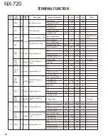
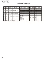
TERMINAL FUNCTION
8pin Modular Connector Specifi cation
Pin
No.
Pin
Name
I/O
Signal
Type
Description/port type
Item and Condition
Min
Typ
Max
Unit
Note
1
MBL
O
Digital
CMOS output
VOH
4.2
5.2
V
VOL
-
0.8
V
2
SB
O
Power
Switched B output
Output Voltage
This parameter depends on Bat-
tery voltage.
Output Current
200
mA
3
GND
-
GND
Ground
Allowable current value
200
mA
4
PTT
I
Digital
CMOS input
(Pull Up: 5.0V/10k
)
VIH
4.2
5.0
V
VIL
0
0.8
V
TXD
O
Digital
CMOS 3-State Buffer
output
(Pull Up: 5.0V/10k
)
VOH
4.2
5.2
V
VOL
-
0.8
V
Baud rate
-
1
9
200
bps
5
ME
-
GND
MIC Ground
MIC Ground
This is ground port for Micro-
phone.
6
MIC
I
Analog Audio input
Output Amplitude
(1kHz, 60% deviation)
-
5
-
mVrms
Coupling Capacitor
-
10
-
uF
Input impedance
-
600
-
Allowable Frequency
300
3000
Hz
7
HOOK/
RXD
I
Digital
DTC144EE input
(Pull Up: 5.0V/4.7k
)
VIH
4.2
5.0
V
VIL
0
0.8
V
Baud rate
-
115200
bps
8
DM
I
Digital
CMOS input/output
(Pull Up: 5.0V/47k
)
VIH
4.2
5.0
V
VIL
0
0.8
V
O
Digital
VOL
-
0.8
V
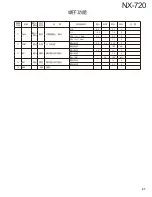
15pin D-sub Connector Specifi cation
Pin
No.
Pin
Name
I/O
Signal
Type
Description
Item and Condition
Min
Typ
Max
Unit
Note
1
SB
-
Power
Switched B output
Voltage
This parameter depends on Bat-
tery voltage.
Supply Current
-
-
2.0
A
(with KCT-60)
-
-
0.5
A
2
IGN
I
Digital
Ignition sense input
Input Voltage
10.8
-
16
V
3
SP2/PA
O
Analog Speaker output
Audio output
3
4
-
W
at 4
, 10% Dis-
tortion
Coupling Capacitor
-
330
-
uF
RL
4
-
-
Allowable Frequency
300
-
3000
Hz
Summary of Contents for NEXEDGE NX-720
Page 122: ...NX 720 ...