Instructions for use - Installation advice
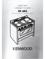
MAXI OVEN
CERAMIC COOKER
CK 680
Page 1: ...Instructions for use Installation advice MAXI OVEN CERAMIC COOKER CK 680 ...
Page 2: ...2 ...
Page 3: ...ooking Hob Key 6 Control Panel 7 How to use the cooking hob 8 12 How to use the multi function oven 13 18 How to use and set the electronic programmer 19 22 Cleaning maintenance 23 27 Advice For The Installer 28 Installation 29 31 Electrical installation 32 33 Service Guarantee 34 ...
Page 4: ...ourself or to others in the event that doubts should arise relating to its operation This appliance must be used only for its intended purpose that is for the domestic cooking of foodstuffs Any other form of usage is to be considered as inappropriate and therefore dangerous The manufacturer declines all responsibility in the event of damage caused by improper incorrect or illogical use of the appl...
Page 5: ...n the prox imity of the cooker cannot come into contact with the hob or become entrapped in the oven door Do not line the oven walls with alu minium foil Do not place baking trays or the drip tray on the base of the oven chamber Do not allow heavy or sharp objects to drop on the glass ceramic hob If the hob is cracked or otherwise dam aged by falling objects etc discon nect the electrical power co...
Page 6: ...rcuits cooking zone Ø 145 1200 W 3 Oval cooking zone Ø 145 x 250 1800 1000 W 4 Double cooking zone Ø 210 120 2100 700 W 5 3 circuits cooking zone Ø 145 1200 W 6 Cooking zone residual heat indicators Attention Disconnect the appliance from the mains if the ceramic hobs is cracked 1 COOKING HOB ...
Page 7: ...oking zone control knob 4 Rear left cooking zone control knob 5 Front left cooking zone control knob 6 Multifunction oven temperature knob 7 Multifunction oven switch knob 8 Electronic programmer Pilot lamps 9 Oven temperature indicator light 10 Cooking hob ON indicator light Fig 2 1 A U T O 8 7 5 4 3 2 1 6 2 CONTROL PANEL 10 9 ...
Page 8: ...hat the glass stays cool at only a few centimeters from the cooking plate The 5 cooking zones are shown by paint ed disks on the ceramic surface 3 CIRCUIT RADIANT ZONES Incorporating 3 heating elements fig 3 2 you can control and light up all 3 together or separately by selecting from the 6 positions on the control knob fig 3 1 The working temperature required is reached in a very short time 6 5 4...
Page 9: ... con trolled by a continuous energy regulator from 1 to 12 maximum temperature fig 3 3 By switching on the second element fig 3 4 and 3 5 the surface area of the rear right and central radiant zones can be extended For this purpose turn the control knob fig 3 3 fully to the right position 1 2 3 4 5 6 7 8 9 1 0 1 1 1 2 Fig 3 3 fig 3 5 fig 3 4 Second element Second element ...
Page 10: ...isotto Browning of meats roasted potatoes fried fish omelettes and for boiling large quantities of water Fast frying grilled steaks etc Switching on the second element Double and oval radiant plate only 0 Knob setting 1 2 3 4 5 6 2 0 1 2 2 3 4 3 4 6 7 4 7 8 4 5 8 9 10 6 11 12 After a short period of use experience will teach you which setting is the right one for your needs CO0KING HINTS Cooking p...
Page 11: ...n required for cooking You should only use pots and pans with flat bases pans with the test mark for glass ceramic hobs are available from specialist shops The diameter of the pan should match that of the cooking plate or be slightly bigger to make the most of the energy Since the cooking surface will stays hot for a certain time after the plate has been switched off you can switch it off 5 or 10 ...
Page 12: ...king foil or plastic materi als on the ceramic surface when it is hot Remember that the surface remains hot for a long time about 30 min after the cooking plate has been switched off Follow the cleaning instructions careful ly Do not use the glass surface for storage CLEANING Before you begin cleaning make sure that the appliance is switched off Remove spillages and other types of incrustations Du...
Page 13: ...es with warm water and washing up liquid WARNING The door is hot use the handle OPERATING PRINCIPLES Heating and cooking in the MULTI FUNCTION oven are obtained in the fol lowing ways a by normal convection The heat is produced by the upper and lower heating elements b by forced convection The circular heating element and fan constantly circulate heated air over the food in the oven for a more rap...
Page 14: ...required temperature The elements will turn ON or OFF auto matically according to the energy need which is determined by the thermostat TRADITIONAL CONVECTION COOKING The upper and lower heating elements are switched on The heat is diffused by natural convection and the temperature must be set between 50 C and 225 C It is necessary to preheat the oven before adding the foods to be cooked Recommend...
Page 15: ...ng etc HOT AIR COOKING The circular element and the fan are on The heat is diffused by forced convection and the temperature must be set between 50 and 225 C It is not necessary to preheat the oven Recommended for For foods that must be well done on the outside and tender or rare on the inside i e lasagna lamb roast beef whole fish etc DEFROSTING FROZEN FOODS Only the oven fan is on To be used wit...
Page 16: ...en 50 and 175 C for max 30 minutes It is necessary to preheat the oven for about 5 minutes Use with the oven door closed Attention the oven door becomes very hot during operation Keep children away For correct use see GRILLING AND AU GRATIN Recommended for For grill cooking when a fast outside browning is necessary to keep the juices in i e veal steak steak hamburger etc CONVECTION COOKING WITH VE...
Page 17: ... FOODS The MULTI FUNCTION oven set on position and gives simultaneous cooking of different foods Different foods such as fish cake and meat can be cooked together without mixing the smells and flavours This is possible since the fats and vapors are oxidized while passing through the electrical element and therefore are not deposited onto the foods The only precautions to follow are The cooking tem...
Page 18: ...0mins ROAST MEATS Beef medium joint 190 5 20 25 mins lb 20mins Lamb 190 5 25 30mins lb 25mins Pork 190 5 30mins lb 30mins Chicken 190 5 20 25mins lb 30mins Turkey 180 4 15 20mins lb 20mins Stews Casseroles 170 3 11 2 2hours COOKING GUIDE Temperature and times given are approximate as they will vary depending on the quality and amount of food being cooked Remember to use ovenproof dishes and to adj...
Page 19: ...ven cooking Program for semi automatic oven cooking Fig 5 2 Fig 5 1 Description of the illuminated symbols AUTO flashing Programmer in auto matic position but not pro grammed AUTO always lit Programmer in auto matic position with program set Automatic cooking taking place Timer in operation and AUTO flashing Program error The time of day lies between the calculated cooking start and end time Note ...
Page 20: ...n the desired time in the panel fig 5 4 Having finished the setting the clock hour will appear on the panel and the symbol will be lit The countdown will start immediately and may be seen at any moment on the panel by simply pressing the button At the end of the time the symbol will be switched off and an intermittent buzzer will go off this can be stopped by pressing any of the buttons SETTING TH...
Page 21: ...e programming that is the the cooking cycle has been super imposed on the clock In this case change the end of cooking time or the cooking time itself by following the instructions above 3 Set the temperature and the cooking program see the relevant sections Once the oven is programmed it will switch on automatically at the right time to stop the cooking at the desired end time During cooking the ...
Page 22: ...the symbol will be on Then set the temperature and the cook ing program see the relevant sections The oven is switched on and it will switch off automatically at the end of the desired time During cooking the symbol remains on and by pressing the button you can see the time that remains until the end of the cooking The cooking program can be can celled at any moment by pushing the button At the en...
Page 23: ...ve products Dry preferably with a soft cloth Acidic substances like lemon juice tomato sauce vinegar etc can damage the enamel if left in contact for too long STAINLESS STEEL SURFACES The stainless steel front panels on this cooker facia oven door storage compartment are protected by a finger print proof lacquer To avoid damaging this lacquer do not clean the stainless steel with abrasive cleaners...
Page 24: ... order to dismantle ADVICE FOR USE AND MAINTE NANCE OF SELF CLEANING PANELS The self cleaning panels are covered with a special microporous enamel which absorbs and removes oil and fat splashes during normal baking over 200 C If after cooking very fatty foods the panels remain dirty operate the oven empty on max temperature for about 30 minutes These panels do not require to be cleaned however it ...
Page 25: ...aced on its wire shelf support fig 6 4 then inserted into the side runners fig 6 3 OVEN FLOOR The oven floor F fig 6 3 can be easily removed to facilitate cleaning Remember to replace the floor correctly afterwards Be careful not to confuse the tray L with the oven floor F ...
Page 26: ... in the oven or in the storage com partment OVEN DOOR The internal glass panel can be easily removed for cleaning by unscrewing the 2 retaining screws Fig 6 5 STORAGE COMPARTMENT The storage compartment is accessible through the pivoting panel fig 6 6 ...
Page 27: ...ining rings to the hooks on the left and right hinges fig 6 7B Hold the door as shown in fig 6 7 Gently close the door and withdraw the lower hinge pins from their location fig 6 7C Withdraw the upper hinge pins from their location fig 6 7D Rest the door on a soft surface To replace the door repeat the above steps in reverse order REMOVING THE OVEN DOOR ...
Page 28: ... observation of the instructions supplied by the manufac turer Always disconnect the cooker from mains power supply before carrying out any main tenance operations or repairs Some appliances are supplied with a protective film on steel and aluminium parts This film must be removed before using the appliance Advice for the installer ...
Page 29: ...e housed in heat resistant units The walls of the units must be capable of resisting temperatures of 75 C above room temperature Do not install the appliance near inflammable materials eg curtains If the cooker is located on a pedestal it is necessary to provide safety measures to pre vent it falling out 50 mm 500 mm 750 mm 450 mm Fig 7 1 7 INSTALLATION ...
Page 30: ...s important to observe the prescrip tions of figures 7 3 7 4 BACKGUARD Before installing the cooker assemble the backguard V fig 7 5 Please note that The backguard V can be found packed at the rear of the cooker Before assembling remove any protective film adhesive tape The backguard must be fixed to the cooktop using the three sup ports B supplied with the appli ance see fig 7 5 V A B Fig 7 5 ...
Page 31: ... WARNING When moving the cooker to its final posi tion DO NOT DRAG fig 7 8 Lift feet clear of floor fig 7 6 MOVING THE COOKER WARNING When raising the cooker to an upright position always ensure that two peo ple carry out this manoeuvre to pre vent damage to the adjustable feet fig 7 6 Fig 7 6 Fig 7 8 Fig 7 7 ...
Page 32: ...ry The manufacturer declines all responsibility for any inconve nience resulting from not observing this condition GENERAL Connection to the mains must be carried out by qualified personnel in accordance with current regulations The appliance must be connected to the mains checking that the voltage corresponds to the value given in the rating plate and that the electrical cable sections can withst...
Page 33: ...earth cables to terminal B according figure 8 2 and 8 3 Pull the feeder cable and block it with the cable clamp D Re mount shield A N B The earth conductor must be left about 3 cm longer than the others A D B Fig 8 1 PE 1 2 3 4 5 N L2 L1 230 V Fig 8 2 FEEDEER CABLE SECTION TYPE H05RR F 230 V 3 x 6 mm2 Connection with wall box connection Contemporaneity factor applied 2 3 4 5 1 230 V N L2 PE L1 Red...
Page 34: ... is not second hand it has not been used commercially you have not fitted a plug incorrectly and you supply your receipt to show when you brought it The appliance has been installed as per the instructions contained within this booklet This guarantee does not affect your statutory rights GUARANTEE AFTER SALES SERVICE If you require After Sales Service contact the MASTERCARE Domestic Appliance Help...
Page 35: ...et are given as simply indicative The manufacturer reserves the right considering the characteristics of the models described here at any time and without notice to make eventual necessary modifications for their construction or for commercial needs ...
Page 36: ...code 1101990 ß6 Part Number 54069 1 ...