background image


KENDRION 

INDUSTRIAL BRAKES 

EEX Line 

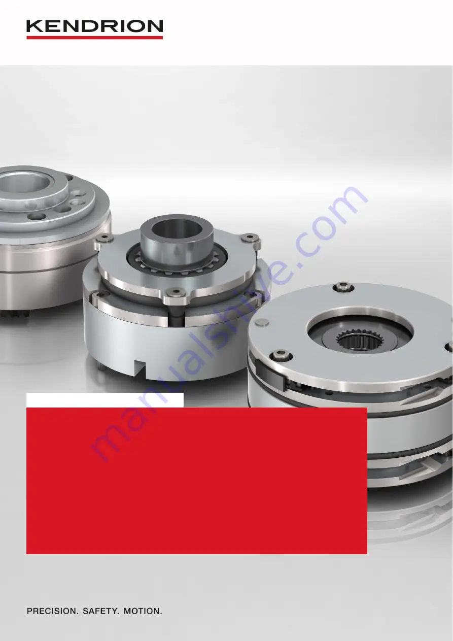
Spring-applied single-disc brake 

Operating Instructions 76..G..B00 

Types: 76 14G10B00  76 16G10B00 76 24G10B00  76 26G10B00 


76 14G11B00 7616G11B00  76 24G11B00  76 26G11B00 


76 14G13B00 76 16G13B00 76 24G13B00  76 26G13B00 


76 14G16B00 76 16G16B00 76 24G16B00  76 26G16B00 


76 14G19B00 76 16G19B00 76 24G19B00  76 26G19B00 


76 14G24B00 76 16G24B00 76 24G24B00  76 26G24B00 

Summary of Contents for 76 14G10B00

Page 1: ...B00 Types 76 14G10B00 76 16G10B00 76 24G10B00 76 26G10B00 76 14G11B00 7616G11B00 76 24G11B00 76 26G11B00 76 14G13B00 76 16G13B00 76 24G13B00 76 26G13B00 76 14G16B00 76 16G16B00 76 24G16B00 76 26G16B00...

Page 2: ...3 3 2 Microswitch 13 and thermoswitch 11 12 connection 14 3 4 Electromagnetic compatibility 15 3 5 Set up and start up 17 3 6 M2 rated torque adjustments 18 4 Maintenance 19 4 1 Checks and service 19...

Page 3: ...components in the following sections 1 2 Standards and directives The state of the art brakes have been designed built and tested in accordance with the requirements of DIN VDE 0580 concerning electr...

Page 4: ...elm Binder Str 4 6 to compile the Kendrion Villingen GmbH 78048 Villingen Schwenningen documentation Wilhelm Binder Str 4 6 Germany 78048 Villingen Schwenningen Germany Applied harmonized standards an...

Page 5: ...magnetic devices and components EN 60079 0 2012 A11 2013 Explosive atmospheres IEC 60079 0 2011 modified IS1 2013 Part 0 Equipment General requirements EN 60079 1 2014 Explosive atmospheres IEC 60079...

Page 6: ...quipment General requirements EN 60079 1 2014 Explosive atmospheres IEC 60079 1 2014 Part 1 Equipment protection by flameproof enclosures d EN 60079 7 2015 Explosive atmospheres IEC 60079 7 2015 Part...

Page 7: ...he spring force generated by the compression springs 4 35 the friction disc 5 is pressed over the armature 2 against the friction plate 33 and flange 3 to generate the braking effect of the spring app...

Page 8: ...lip outer ring 29 1 Cam 6 Spacer sleeve 15 Circlip inner ring 30 Cable gland 7 Cover 16 O ring 30 1 Cap nut 8 Mounting surface 17 Hub 30 2 Connector sleeve 9 Flat seal 18 Deep groove ball bearing 30 3...

Page 9: ...Operating Instructions BA 76 G B00 Last updated 13 03 2020 Page 9 of 34 Fig 9 1 Spring applied single disc brake 76 26G B00 Rated air gap...

Page 10: ...ll bearing 18 is not distorted during installation of the spring applied single disc brake and that the shaft rotates easily when the brake is released Check that there are no grinding sounds Size 10...

Page 11: ...Check that the mechanical hand release 29 is in a central position see Fig 9 1 when not in use This is crucial to ensure reliable brake engagement Otherwise the full braking effect of the spring appli...

Page 12: ...switching type DC side switching or AC side switching Bridge rectification Bridge rectifiers provide voltage with minimum residual ripple This means that brake humming can be avoided even if small si...

Page 13: ...gested wiring of brake and safety switches circuit diagram N M 3 2 1 4 3 5 L1 L2 L3 Built in rectifier Brake field coil 1 2 Control relay for brake Safety switches microswitch contacts only brake type...

Page 14: ...entries and the terminal box are suitably sealed to ensure compliance with the protection class requirements to EN 60529 3 3 2 Microswitch 13 and thermoswitch 11 12 connection The four 2x2 thermoswit...

Page 15: ...d interference during brake operation must be minimized Since the brake features depend on the circuitry and operation a declaration of conformity with the applicable EMC standard can only be furnishe...

Page 16: ...0 may cause the brake to be de energized temporarily Consequential damage as described under a above must be avoided by the user by taking adequate precautions Electromagnetically engaged systems Volt...

Page 17: ...asional explosion hazard Zone 2 occasional explosion hazard for short periods Zone 21 occasional explosion hazard caused by combustible dust in normal operation Zone 22 explosion hazard caused by comb...

Page 18: ...brake or electronic accessories Such damage may not be apparent immediately DC side brake switching without protective circuit as described in Section 3 4 will cause damage to electronic rectifiers el...

Page 19: ...he gap widths may have to be narrower than those specified in Table 2 3 of EN 60079 1 2014 Warning In case the explosion protection features of the spring applied brake are damaged during maintenance...

Page 20: ...d torque make sure that the socket head cap screws 32 project from the flange 3 by the length xnom approximate value see Table 18 1 The self locking nuts 31 to ISO 10511 04 A2F 140 C must be replaced...

Page 21: ...eplaced when the maximum service life switching operations has been reached Replacement must be carried out by the manufacturer or by a specialist repair shop due to the complex installation of the th...

Page 22: ...4 602633 304046 13 73 24116E00400 76 24E11B00044 602635 3040071 16 73 24116E00400 76 24E11B00044 602635 304071 19 76 14124E00400 76 24124E05400 5 76 24E11B00044 602637 304107 24 76 14124E00400 76 2412...

Page 23: ...ronmental conditions for storage and transport as specified in EN IEC 60721 3 1 and EN IEC 60721 3 2 6 Emissions 6 1 Noise The spring applied single disc brake produces switching noise during engageme...

Page 24: ...orrect faults if found Brake engagement failure Voltage applied to field coil in unpowered condition too high residual voltage Check whether residual voltage is applied to the field coil and correct f...

Page 25: ...y electric motors for use on industrial plant and more specifically in potentially explosive atmospheres The brakes must be used in accordance with the operating requirements detailed in this manual T...

Page 26: ...of the products may cause interference outside the brake or even feedback to the brake in case of adverse installation conditions Should you have queries concerning mounting and fitting conditions ple...

Page 27: ...ed out by qualified specialist personnel in accordance with EN 50110 1 EN 50110 2 IEC 60364 1 Failure to perform repairs according to requirements may cause serious personal injury or equipment damage...

Page 28: ...ween power off and power on Total cycle time t7 coil ON time plus coil OFF time Duty cycle percentage relationship of coil ON time to total cycle time Switching operation one complete switching on and...

Page 29: ...voltage specified by the manufacturer for voltage windings to identify the device or component Rated current IB amperage determined by the manufacturer for the specified operating conditions Unless ot...

Page 30: ...ax 6 mm 0 7 0 7 0 9 0 9 1 1 1 1 Standard rated voltage VAC 230 Temperature class T5 to IEC EN 60079 0 Insulation class F Pollution degree 2 Protection to EN 60529 IP 67 brakes with dust explosion prot...

Page 31: ...the current load K 2 5 at 1 5 A 8 0 at 2 5 A Table 31 1 Thermoswitch specifications Rated operating conditions Rated voltage tolerance 10 Frequency range 1 of rated frequency Ambient temperature 13 C...

Page 32: ...for the switching torque M1 and the transmissible torque M4 may differ from the specified M2 values The switching torque M1 depends on the speed rpm If the friction surfaces are contaminated with oil...

Page 33: ...to identify the brake version consists of the type number followed by the 4 digit version number Individual brake types may be available in different versions So the version number identifies the rele...

Page 34: ...Betriebsanleitung 76 43119H03 Operating Instructions BA 76 G B00 Last updated 13 03 2020 Page 1 of 34...

Reviews:

Related manuals for 76 14G10B00