background image

MasterTig 535ACDC

Operating manual - EN

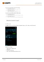
3.2.6 Current mode view

To adjust parameters:

1.

Go to the

Current mode

view.

2.

Turn the control knob (1) to browse through the parameters.

3.

Select a parameter to be adjusted by pressing the control knob (1).

4.

Adjust the parameter by turning the control knob (1).

5.

Close the parameter setting by pressing the control knob (1).

Adjustable parameters:

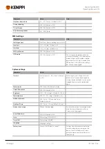
Parameter

Value

Current mode

DC- / DC+ / AC / MIX

AC Waveform

Square / Optima / Sine (Default = Optima)

AC Frequency

30 Hz ... 250 Hz, step 1.0 Hz

AC+ / AC- balance

Min/Max = -60 % ... 0 %, step 1 % (Default = -25%)

MIX TIG AC ratio

Min/Max = 10 % ... 90 %, step 1 % (Default = 50 %)

MIX TIG cycle time

Min/Max = 0.1 s ... 1.0 s, step 0.1 s (Default = 0.6 s)

MIX TIG DC level

Min/Max = 50 % ... 150 %, step 1 % (Default = 100 %)

© Kemppi

43

1921940 / 2140

Summary of Contents for 535ACDCG M

Page 1: ...MasterTig 535ACDC Operating manual EN MasterTig 535ACDC MasterTig Cooler MXL Kemppi 1 1921940 2140...

Page 2: ...anel 24 2 11 Lifting MasterTig 535 equipment 28 3 Operation 30 3 1 Operating power source 31 3 2 Operating control panel MTP35X 32 3 2 1 Home view 33 3 2 2 Weld Assist view 34 3 2 3 Memory channels vi...

Page 3: ...MasterTig 535ACDC Operating manual EN 5 5 Ordering info 68 Kemppi 3 1921940 2140...

Page 4: ...imize damage and harm are indicated with the below symbols Read these sections carefully and follow their instructions Note Gives the user a useful piece of information Caution Describes a situation t...

Page 5: ...le 500 A AC DC A dedicated VRD Voltage Reduction Device model version where the VRD function is locked on is also available Control panel MTP35X control panel AC DC 7 TFT LCD display panel Equipment 1...

Page 6: ...location on the device It is important to make correct reference to the serial number of the product when ordering spare parts or making repairs for example Quick Response QR code Device related infor...

Page 7: ...not damaged Before you install the power source on site see the requirements for the mains cable type and fuse rating given in the Technical data on page 57 chapter Distribution network MasterTig 535A...

Page 8: ...o install the mains cable and plug Do not connect the machine to the mains before the installation is complete Install the 3 phase plug according to the MasterTig power source and site requirements Re...

Page 9: ...r to Installing equipment on cart optional on page 12 The cooling unit must be installed by authorized service personnel Do not attempt to move the power source with a hoist from its handle The handle...

Page 10: ...he power source with a hoist from the lifting eyes and place it on top of the cooling unit so that the fixing plates align and go into their slots Fix the units together with two screws in the front a...

Page 11: ...the rear cover back 5 Fill the cooling unit with cooling liquid MasterTig Cooler MXL tank volume is 3 litres and the recommended coolant is MPG 4456 Kemppi mixture Avoid cooling liquid contact with s...

Page 12: ...tional There is a 4 wheel transport unit available for use with the MasterTig welding equipment Tools needed 1 Install the cooling unit on the cart 2 Fix the cooling unit to the cart with two screws M...

Page 13: ...ey remain accessible through the next steps 4 Install the power source on top of the cooling unit Refer to Installing cooling unit optional on page 9 for install ation details 5 Secure the power sourc...

Page 14: ...rating manual EN 6 Secure the equipment to the cart with the rear connection bracket Rear screws M8x16 top screws M5x12 For lifting the equipment refer to Lifting MasterTig 535 equipment on page 28 Ke...

Page 15: ...nectors clockwise Water cooled TIG torch The cooling unit must already be installed and in place at this stage Refer to Installing cooling unit optional on page 9 1 Assemble the TIG torch according to...

Page 16: ...MasterTig 535ACDC Operating manual EN Tip For Kemppi welding torches refer also to userdoc kemppi com Kemppi 16 1921940 2140...

Page 17: ...reduce the risk of injury to users or damage to electrical equipment 1 Connect the earth return cable to the negative connector on the power source 2 Ensure the earth return clamp is secured tightly...

Page 18: ...lder to the positive connector on the power source 2 Connect the earth return cable to the negative connector on the power source 3 Ensure the earth return clamp is secured tightly to the work piece o...

Page 19: ...n the Remote mode is selected on the control panel and both wireless and wired remotes are connected the wired remote will be used Refer to the and signs on the battery holder and in the remote for th...

Page 20: ...nected the blue LED on the left of the connection button is lit The green LED blinks when the battery is low 5 To enable remote operation select Remote mode in the control panel settings Remote contro...

Page 21: ...the control panel settings 3 Keeping the wireless remote close to the power source long press 3 sec the wireless remote pairing button on the foot pedal 4 Once connected the blue LED next to the butt...

Page 22: ...y set this will increase the risk of defects in the weld weld porosity Spark ignition becomes more difficult if the gas flow is too high Contact your local Kemppi dealer for choosing the gas and the e...

Page 23: ...ttle mounting 2 Move the gas bottle onto the rack Tilt the gas bottle back and pull the cart towards the gas bottle and push the top of the gas bottle forwards The pivot plate assists to lift the bott...

Page 24: ...l Tools needed T20 Detaching control panel 1 Detach the control panel and frame from the power source Remove the fixing screws at the top and bottom of the panel First pull the top of the control pane...

Page 25: ...ect the control panel s cable 3 Remove the control panel from the frame Release the clips at the top by pressing the panel from the outside Release one clip at the bottom rotate the panel slightly and...

Page 26: ...that the panel is firmly attached to the frame 2 Connect the new control panel s cable 3 Mount the control panel in place Insert the bottom of the panel in the slot first Push the top of the panel fi...

Page 27: ...MasterTig 535ACDC Operating manual EN Kemppi 27 1921940 2140...

Page 28: ...the local regulations Connect the 2 legged chain or strap from the hoist hook to the two lifting eyes on the power source Ensure the chain or strap is long enough to avoid excessive lateral load on t...

Page 29: ...ment is properly secured to the cart 2 Connect the 4 legged chain or straps from the hoist hook to the four lifting points on the cart on both sides of the welding equipment If a gas bottle is install...

Page 30: ...vicinity If the welding equipment is left unused for a longer period disconnect the mains plug from the mains Do not use the mains plug as a power ON OFF switch Always check before use that interconn...

Page 31: ...ng power source 1 Turn the power source ON The power switch is located in the rear 2 Wait approximately 15 seconds for the system to start up For control panel operation refer to Operating control pan...

Page 32: ...parameter s value The control knob functions also as a push button when the green light is lit in the knob center Used to navigate through the control panel views and selections 2 Menu button left fu...

Page 33: ...view is the control panel work mode after the initial machine and control panel start up When in Home view the welding current can be adjusted directly by turning the control knob Depending on your we...

Page 34: ...er source models where the VRD function is locked on VRD symbol red blinking There is a fault with VRD that prevents welding VRD symbol off VRD is off Tip You can switch between the home view and the...

Page 35: ...joint edge joint lap joint fillet joint tube joint tube plate joint The welding position PA PB PC PD PE PF PG With MasterTig DC power sources the aluminum Al selection is not available as a welded ma...

Page 36: ...equency AC and Start stop parameters Set to default All these parameters can still be modified as per normal for the actual welding Weld Assist gives you a recommendation for these Shielding gas flow...

Page 37: ...rol knob button 2 Select The electrode type Fe Basic Fe Rutile High Eff Ss stainless steel Inox The electrode diameter 1 6 6 mm The welding joint type butt joint corner joint lap joint fillet joint tu...

Page 38: ...rity in this case the electrode holder is connected to the positive DIX connector All these parameters can still be modified as per normal for the actual welding 3 2 3 Memory channels view Memory chan...

Page 39: ...ob 1 to highlight a channel 2 Open the channel actions menu by pressing the control knob button 1 The available actions are shown Cancel Save changes Save to and Delete 3 Select an action with the con...

Page 40: ...arameters in continuous welding Parameter Value Note Pre gas 0 0 s 10 0 s Auto step 0 1 s Default Auto Search arc OFF 5 90 step 1 Default OFF Upslope OFF 0 1 s 5 0 s step 0 1 s Default OFF Hot start l...

Page 41: ...tep 1 Default 1 If Lift TIG is used MicroTack graph shows only 1 spot and the spot count para meter is not visible MicroTack spot time 1 ms 200 ms step 1 ms Default 10 ms MicroTack pause time 10 0 ms...

Page 42: ...and adjustable In AC current mode only OFF or Manual can be selected Average current Min Current limit min Max Machine specific These values depend also on other pulse parameters Maximum average curre...

Page 43: ...urning the control knob 1 5 Close the parameter setting by pressing the control knob 1 Adjustable parameters Parameter Value Current mode DC DC AC MIX AC Waveform Square Optima Sine Default Optima AC...

Page 44: ...ngs groups and parameters 3 Select a parameter to be adjusted or changed by pressing the control knob button 1 4 Adjust or change the setting by turning the control knob 1 5 Close the parameter settin...

Page 45: ...omatically when selec ted New pairing information replaces the old information Pairing status is shown as the settings value TIG settings Parameter Value Note Balance limit min 99 0 step 1 Default 60...

Page 46: ...0 s Activating this starts the gas test with default time Time can be changed by turning the control knob Gas test can be stopped by pressing the control knob again Water cooler OFF Auto ON Default Au...

Page 47: ...405 A 400 V step 1 A Default MMA maximum current of the power source 8 A 385 A 220 V step 1 A Default MMA maximum current of the power source Welding processes and features on page 62 3 2 8 Info view...

Page 48: ...t the control panel cable The power source and control panel must be turned on 4 Connect the USB memory stick to the USB connector on the rear side of the control panel The control panel detects your...

Page 49: ...s front This activates a pump motor which pumps the cooling liquid into the hoses and to the welding torch 3 Observe the cooling system throughout the cooling liquid circulation process The cooling li...

Page 50: ...emote control optional on page 19 Hand remote control To adjust the welding current turn the knob on the remote control Tip The remote control comes equipped with a handy clip for hanging the remote o...

Page 51: ...MasterTig 535ACDC Operating manual EN Tip To shift the foot pedal position on the floor use the foot pedal handle Kemppi 51 1921940 2140...

Page 52: ...charging the capacitor Check the electric connectors of the unit at least every six months Clean oxidized parts and tighten loose connectors Use the correct tension torque when fastening loose parts C...

Page 53: ...m current the lower one of these is the maximum current that can be used Make sure the coolant circulation is working normally see the coolant circulation warning LED on the power source Measure the c...

Page 54: ...emperature Do not turn off the cooler Let the liquid circulate until the fans cool it down If fans are not running contact Kemppi service 26 Cooling liquid not circulating No cooling liquid or circula...

Page 55: ...son Proposed action 244 Internal memory failure Initialization failed Restart welding system If problem persists contact Kemppi service 250 Internal memory failure Memory communication failed Restart...

Page 56: ...ctronic equipment and their implementation in accordance with national law electrical equipment that has reached the end of its life must be collected separately and taken to an appropriate environmen...

Page 57: ...EN 5 TECHNICAL DATA Technical data Power source MasterTig 535ACDC on the next page Cooling unit MasterTig Cooler MXL on page 60 Additional information For ordering information refer to Ordering info...

Page 58: ...40 C Duty cycle and process specified in the next column 40 TIG 500 A 30 V 400 V 450 A 28 V 220 V 60 TIG 400 A 26 V 400 V 400 A 26 V 220 V 100 TIG 300 A 22 V 400 V 300 A 22 V 220 V 40 MMA 380 A 35 2...

Page 59: ...pe Remote Analog CAN BUS Kemppi Remote Bus Arc striking voltage 5 11 kV Stick electrode diameters mm 1 6 7 0 mm TIG welding cable connection type R1 4 Standards IEC 60974 1 3 10 AS 60974 1 3 GB T 1557...

Page 60: ...power at 1 l min 1 7 kW Cooling power at 1 l min 1 7 kW Recommended coolant MPG 4456 Kemppi mixture Coolant pressure max 0 4 MPa Tank volume 3 0 l Operating temperature range 20 40 C Storage temperat...

Page 61: ...m number mm l min Argon 15 90 1 6 4 5 6 6 5 8 0 9 5 6 7 20 150 2 4 6 7 9 5 11 0 7 8 30 200 3 2 7 8 10 11 0 12 5 16 8 10 40 350 4 0 10 11 16 17 5 10 12 95 460 4 8 10 12 16 19 12 18 TIG welding DC Weldi...

Page 62: ...tween pos itive and negative Used especially in aluminum welding AC Waveform Function to change the wave form of the alternating current in AC TIG welding Three options are available sine square and O...

Page 63: ...s pulsed in two different frequencies slow and fast The fast fre quency makes the arc more focused and the slow frequency produces a nice fish scale appearance to welds Downslope Welding function that...

Page 64: ...Place to store predefined welding parameter settings A welding machine can include a number of preset channels Users can create new channels for their own welding jobs and modify or delete them Makes...

Page 65: ...ignition with TIG Positive ignition current Adjusts the current level of the positive ignition sequence Only in ACDC power sources TIG Positive ignition time Adjusts the length of the positive igniti...

Page 66: ...ck welds for example joining thin sheets with low heat input Startup level The point of welding current where the upslope begins T Tail arc Welding function that allows using a brief low current perio...

Page 67: ...is preset by the user The value zero means the function is off V VRD voltage reduction device A safety device used in welding equipment to reduce the open circuit voltage to maintain below a certain v...

Page 68: ...dering info For ordering information and optional accessories refer to Kemppi com For connection options of all gun and torch models and corresponding remote controls refer to Kemppi Userdoc at https...

Reviews: