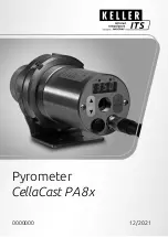
Keller CellaCast PA8 Series Manual Download Page 1

Pyrometer 

CellaCast PA 8x

0000000 12/2021

Summary of Contents for CellaCast PA8 Series

Page 1: ...Pyrometer CellaCast PA8x 0000000 12 2021...

Page 2: ......

Page 3: ...en Ausgangsleitung 1 0 mW bei einer Wellenl nge 630 680 nm Das Ger t nicht unbeaufsichtigt lassen wenn der Laser aktiviert ist Den Laserstrahl des Ger tes nicht auf Personen richten Bei der Montage un...

Page 4: ...bar Es ist schmutz und lfreie Druckluft zu verwenden Bei einer zu erwartenden Umgebungstemperatur von 65 C ist eine K hlung notwendig 1 Messfeldgr e 2 Gie strahl 3 Sichtbereich 4 Messabstand 6 Montag...

Page 5: ...4 V 0 24 V 0 10 V Schirm Digital IN OUT1 IN OUT2 Analog OUT1 OUT2 Analog IN 1 2 3 4 5 6 7 8 Pin 1 WH wei L Spannungsversorgung 24V DC Pin 2 BN braun Schaltein ausgang 1 Pin 3 GN gr n Stromausgang 2 Sp...

Page 6: ...vierung dr cken Sie die Mode Taste an der Geh u se R ckseite f r ca 2 s Alternativ kann der Laser ber die Schnittstelle eingeschaltet werden Zum Fokussierung drehen Sie die Optik bis das Pilotlicht al...

Page 7: ...ion nicht m glich kann die Fokussierung auch au erhalb der Anlage erfolgen Hierf r das Pyrometer auf die gleiche Distanz einstellen wie die Distanz Pyrometer zum Gie strahl 9 Parametrierung Das Pyrome...

Page 8: ...arameter t Act angezeigt wird Mode Taste dr cken Im Display wird Wert f r die aktuelle Messzeit oder Auto angezeigt Taste oder f r 2 s dr cken Die Anzeige blinkt 3 mal Taste oder den gew nschten Wert...

Page 9: ...r cken Parametrierung beenden 30 s warten Oder Wechsel mit oder zum Parameter End und mit Mode auf die n chst h here Einstellebene zu wechseln Wechsel mit oder zum Parameter End und Mode Taste dr cken...

Page 10: ...sung durch Das Emissionsgradverh ltnis wird wie folgt eingestellt Taste oder f r 2 s dr cken im Display wird der eingestellte Emissionsgradverh ltnis angezeigt z B 103 0 Taste oder gedr ckt halten bis...

Page 11: ...lb der Reklamations fristen geltend gemacht werden k nnen Verpackung Die Verpackungsmaterialien sind nach umweltvertr glichen und entsorgungstechnischen Ge sichtspunkten ausgew hlt und deshalb recycle...

Page 12: ...ivated Do not point the laser beam at any person During pyrometer installation and alignment make sure to avoid the possibility of laser light reflections caused by reflective surfaces All currently v...

Page 13: ...th a maximum pressure of 6 bars are required for that Use oil free and dirt free compressed air If the expected ambient temperatures are 65 C a cooling system is required 1 Target size 2 Pouring strea...

Page 14: ...4 20 mA 0 24 V 0 24 V 0 10 V shielded Digital IN OUT1 IN OUT2 Analogue OUT1 OUT2 Analogue IN 1 2 3 4 5 6 7 8 Pin 1 WH white L Power supply 24V DC Pin 2 BN brown Digital in out 1 Pin 3 GN green Analogu...

Page 15: ...tate instrument alignment to the target spot To activate the laser press the MODE button on the rear panel for 2 seconds Alternatively the laser can be switched on with the interface To focus rotate t...

Page 16: ...nt To do this set the pyrometer to the same distance as the distance between the pyrometer and the pouring stream 9 Parameterization On delivery the pyrometer is parameterized on a discontinuous pouri...

Page 17: ...displayed Press Mode The current sampling time or Auto is displayed Press or for 2 second The display flashes three times Press or to set the desired sampling time Press Mode to confirm the parameter...

Page 18: ...r Press or to change to the parameter End Then Press Mode to change to the functional menu In the functional menu press or to change to the parameter End then press Mode Alternatively the parameters c...

Page 19: ...vity ratio carry out a new control measurement The emissivity ratio is set as follows Press or for 2 seconds The value of the selected emissivity ration is displayed for example 103 0 Press or until t...

Page 20: ...If the period for filing claims has expired you will no longer be able to make any claims for compensation of damage or loss Packing The packages used are made of carefully selected environmentally co...

Page 21: ...ur d onde 630 670 nm N utilisez le laser que pour l alignement et la focalisation de l instrument Eteignez le une fois cette op ration termin e Ne pas viser le laser sur une personne Lors de l utilisa...

Page 22: ...e Si la temp rature ambiante exc de les 65 C il faut alors utiliser le module de refroidissement 1 Taille de cible 2 Jet de coul e 3 Champ de vis e 4 Distance de travail 6 C ble de fibre optique d ass...

Page 23: ...2 8 L L RS485 0 4 20 mA a 0 4 20 mA 0 24 V 0 24 V 0 10 V shielded Digital IN OUT1 IN OUT2 Analogue OUT1 OUT2 Analogue IN 1 2 3 4 5 6 7 8 Pin 1 WH blanc L 24 V DC Pin 2 BN marron Digital in out 1 Pin...

Page 24: ...disposent d un spot laser qui peut tre activ pour faciliter l alignement de l instrument Pour activer le laser appuyez sur le bouton MODE pendant 2 secondes Alternativement le laser peut tre activ via...

Page 25: ...Pour ce faire r glez le pyrom tre la m me distance que la distance entre le pyrom tre et le jet de coul e 9 Param trage Par d faut le pyrom tre est param tr sur un flux de coul e discontinu Ce param t...

Page 26: ...ou Auto s affiche Appuyez sur la touche ou pendant 2 sec L afficheur clignote 3 fois Appuyez sur la touche ou jusqu la valeur voulue Appuyez sur la touche Mode pour valider Quitter le menu de configu...

Page 27: ...r le menu de configuration Attendre 30 secondes ou Appuyez sur la touche ou pour passer au param tre End Appuyez ensuite sur Mode pour passer au menu fonctionnel Dans le sous menu appuyez sur ou pour...

Page 28: ...uez une nouvelle mesure de contr le Le rapport d missivit est d fini comme suit Appuyez sur ou pendant 2 secondes La valeur de la ration d missivit s lectionn e s affiche par exemple 103 0 Appuyez sur...

Page 29: ...mm diatement Si la p riode de r clamation est d pass e vous ne pourrez plus pr tendre un d dommagement ou un remplacement Emballage L emballage utilis par KELLER HCW respecte l environnement et est pa...

Page 30: ...positivo sin vigilancia cuando el l ser est activado No dirija el rayo l ser del dispositivo hacia personas Evite reflexiones de los rayos l ser debidas a superficies reflectantes durante el montaje y...

Page 31: ...con una presi n m xima de 6 bares Utilice aire comprimido sin aceite ni su ciedad Si la temperatura ambiente esperada es 65 C se requiere un sistema de enfriamiento 1 Tama o del campo de medici n 2 Ch...

Page 32: ...d Digital IN OUT1 IN OUT2 Analogue OUT1 OUT2 Analogue IN 1 2 3 4 5 6 7 8 Pin 1 WH blanco L Alimentaci n el ctrica 24 V Pin 2 BN marr n Entrada y o salida de conmutaci n 1 Pin 3 GN verde Salida de corr...

Page 33: ...posterior de la carcasa durante aproxi madamente 2 s Alternativamente el l ser puede ser encendido a trav s de la interfaz Para enfocar gire la ptica hasta que el puntero se visualice como un punto d...

Page 34: ...planta Para esto ajuste el pir metro a la misma distancia que la distancia desde el pir metro hasta el chorro de vertido 9 Configuraci n de par metros Se entrega el pir metro con los par metros confi...

Page 35: ...tro t Act Pulse la tecla Mode En el display se muestra el tiempo de vertido ajustado actualmente o Auto Presione la tecla o durante 2 segundos La pantalla parpadea 3 veces Presione la tecla o para aju...

Page 36: ...a parameterizaci n Espere 30 segundos o Cambie con o al par metro End y con Mode para cambiar al siguiente nivel de ajuste m s alto Cambie al par metro End con o y pulse el bot n Mode para cambiar a l...

Page 37: ...segundos La pantalla muestra la relaci n de emisividad establecida por ejemplo 103 0 Alternativamente la relaci n de emisividad se puede establecer a trav s de IO Link 11 Transporte embalaje y su eli...

Page 38: ...y por lo tanto son reciclables El embalaje debe eliminarse de forma respetuosa con el medio ambiente Eliminaci n del instrumento al final de su vida til Los residuos de equipos el ctricos y electr ni...

Page 39: ...30 670 nm Non lasciare mai l apparecchio incustodito quando il laser attivato Non puntare il raggio laser dell apparecchio verso persone Durante il montaggio e l allineamento del pirometro evitare i r...

Page 40: ...tilizzare aria compressa priva di polvere e olio In caso di temperatura ambiente prevista 65 C necessario un raffreddamento 1 Dimensione del campo di misura 2 Getto di colata 3 Campo visivo 4 Distanza...

Page 41: ...0 10 V shielded Digital IN OUT1 IN OUT2 Analogue OUT1 OUT2 Analogue IN 1 2 3 4 5 6 7 8 Pin 1 WH bianco L alimentazione tensione 24 V Pin 2 BN marrone Ingresso uscita commutazione 1 Pin 3 GN verde Usci...

Page 42: ...nativa il laser pu essere acceso tramite l interfaccia Per mettere a fuoco ruotare l ottica fino a quando la luce pilota viene proiettata come un punto luminoso nitido e rotondo sull oggetto da misura...

Page 43: ...to posizionare il pirometro alla stessa distanza prevista dal getto di colata ed effettuare la messa a fuoco 9 Parametrizzazione Alla consegna il pirometro viene fornito con i parametri impostati per...

Page 44: ...quando nel display non viene visualizzato t Act Premere il tasto Mode Il display mostra il valore per il tempo di misura corrente o Auto Premere il tasto o per 2 s Il display lampeggia 3 volte Premere...

Page 45: ...to Mode Parametrizzazione finale Aspetta 30 s Oppure Cambiare con o al parametro End e con Mode per passare al livello di imposta zione immediatamente superiore Passare al parametro End con o e premer...

Page 46: ...103 0 Premere il tasto o fino a visualizzare il rapporto di emissivit desiderato Rilasciare il tasto o Il display mostra la temperatura attuale e il nuovo rapporto di emissivit viene salvato In alter...

Page 47: ...e gli aspetti tecnici dello smaltimento pertanto possono essere riciclati L imballaggio deve essere smaltito nel rispetto dell ambiente Smaltimento del vecchio apparecchio In molti casi le vecchie app...

Page 48: ...RU CellaCast PA 8x 1 X 8x CellaCast PA www keller de its 2 3 2 1 0 630 680 4 CellaCast PA 8x...

Page 49: ...RU CellaCast PA 8x 1 5 30 30 50 6 65 C 1 2 3 4 6 125...

Page 50: ...20 mA a 0 4 20 mA 0 24 V 0 24 V 0 10 V shielded Digital IN OUT1 IN OUT2 Analogue OUT1 OUT2 Analogue IN 1 2 3 4 5 6 7 8 Pin 1 WH L 24V Pin 2 BN 1 Pin 3 GN 2 Pin 4 YE 1 Pin 5 GY RS 485 A Tx D Pin 6 PK...

Page 51: ...RU CellaCast PA 8x 8 PA xx AF xx C PA xx AF xx L 2 2 DIN 916 DIN 911 1...

Page 52: ...RU 60 C 2 15 9 5 1 2 1 2 T DEL Qu ATD Q Atd LI 1 1 1100 C LI 2 2 1200 C 1 4 T DEL 2 2 LI 2 5 T ACT 3 1 LI 1 CellaCast PA 8x...

Page 53: ...RU 9 1 PA 83 5 Qu ATD Q Atd T DEL s 1 s T ACT s Auto Mode Ao Qu Mode Q EPS Q ATD Mode t dEl t Act Mode Auto Press for 2 second 3 Mode 30 End Mode End Mode T DEL T DEL CellaCast PA 8x...

Page 54: ...RU 9 2 PA 80 81 15 Qu ATD Q Atd T DEL s 1 s T ACT s 15 s Mode Ao Qu Mode Q EPS Q ATD Mode t dEl t Act Mode 2 3 Mode 30 End Mode End Mode IO Link 10 CellaCast PA 8x...

Page 55: ...RU 1 2 C 101 104 2 103 0 IO Link CellaCast PA 8x...

Page 56: ...RU 11 KELLER HCW IO Link CellaCast PA 8x...

Page 57: ...CN CellaCast PA 8x 1 PA 8x www keller de its 2 3 1 0mW 630 670nm 4 CellaCast PA 8x...

Page 58: ...CN 1 5 30 30 50 6 65 C 1 2 3 4 6 125 7 24V DC 18 32 V DC CellaCast PA 8x...

Page 59: ...mA 0 24 V 0 24 V 0 10 V shielded Digital IN OUT1 IN OUT2 Analogue OUT1 OUT2 Analogue IN 1 2 3 4 5 6 7 8 Pin 1 WH L 24 V DC Pin 2 BN 1 Pin 3 GN 2 Pin 4 YE 1 Pin 5 GY RS 485 A Tx D Pin 6 PK RS 485 B Tx...

Page 60: ...CN PA xx AF xx L 2 2 DIN 911 DIN 916 1 60 C LED 2 15 9 5 s 1 2 1 T DEL 2 CellaCast PA 8x...

Page 61: ...CN Qu ATD Q Atd LI 1 1 1100 C LI 2 2 1200 C 1 4 T DEL 2 2 LI 2 5 T ACT 3 1 LI 1 9 1 PA 83 O 5 Qu ATD Q Atd T DEL 1 s T ACT Auto Mode Ao Qu Mode Q EPS Q ATD Mode t dEl t Act CellaCast PA 8x...

Page 62: ...CN Mode Auto 2 3 Mode 30 End End T DEL T DEL 9 2 SPA 80 81 15 s Qu ATD Q Atd T DEL 1 s T ACT 15 s Mode Ao Qu Mode Q EPS Q ATD Mode t dEl t Act Mode 2 3 Mode CellaCast PA 8x...

Page 63: ...CN 30 End End IO Link 10 1 2 C CellaCast PA 8x...

Page 64: ...CN 101 104 103 0 IO Link 11 KELLER HCW IO Link CellaCast PA 8x...

Page 65: ...KR CellaCast PA 8x 1 PA CellaTemp PA www keller de its 2 3 Class 2 630 670 nm 1 0 mW 4 field of view background CellaTemp PA 8x...

Page 66: ...KR 1 5 30 30 6 bar 50 l min 65 C 1 Target size 2 3 field of view 4 6 125mm CellaCast PA 8x...

Page 67: ...0 4 20 mA a 0 4 20 mA 0 24 V 0 24 V 0 10 V shielded Digital IN OUT1 IN OUT2 Analogue OUT1 OUT2 Analogue IN 1 2 3 4 5 6 7 8 Pin 1 WH L 24V DC Pin 2 BN 1 Pin 3 GN 2 Pin 4 YE 1 Pin 5 GY RS 485 A Tx D Pin...

Page 68: ...KR CellaCast PA 8x 8 through lens target marker PA xx UF xx C PA xx UF xx L MODE 2 MODE 2 DIN 911 DIN 916 O 1...

Page 69: ...60 C LED 2 15 9 5 Limit 1 Limit 2 Limit 1 T DEL Limit 2 Limit Two colour channel Qu ATD function Q Atd Parameter Function Default LI 1 Limit 1 1100 C LI 2 Limit 2 1200 C 1 4 T DEL 2 Limit 2 LI 2 5 T...

Page 70: ...lour channel Qu ATD function Q Atd Parameter Function Default T DEL Time delay s 1 s T ACT Sampling time s Auto Mode Ao Qu Mode Q EPS Q ATD Mode t dEl t Act Mode Auto 2 Mode 30 End Mode function menu...

Page 71: ...PA 8x Two colour channel Qu ATD function Q Atd Parameter Function Default T DEL Time delay s 1 s T ACT Sampling time s 15 s Mode Ao Qu Mode Q EPS Q ATD Mode t dEl t Act Mode 2 Mode 30 End Mode End Mod...

Page 72: ...KR CellaCast PA 8x 1 Ratio correction 2 C 101 104 2 103 0 IO Link 11...

Page 73: ...KR CellaCast PA 8x KELLER HCW IO Link...

Page 74: ......

Page 75: ......

Page 76: ...KELLER HCW GmbH Infrared Temperature Solutions ITS Carl Keller Str 2 10 49479 Ibbenb ren Germany www keller de its...

Reviews: