Section 2: General operation
Model DMM7510 7½ Digit Graphical Sampling Multimeter Reference Manual
2-98
DMM7510-901-01 Rev. B / May 2015
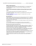
Show voltage readings in decibels
You can show DC or AC voltage in decibels (dB), which compresses a large range of measurements
into a much smaller scope. The relationship between dB and voltage is defined by the following
equation:
Where:
•
V
in
is the DC or AC input signal
•
V
ref
is the specified voltage reference level
If a relative offset value is in effect when dB is selected, the value is converted to dB, and then
relative offset is applied to the dB value. If relative offset is applied after dB has been selected, dB
has relative offset applied to it.
The largest negative value of dB is
−160 dB. This accommodates a ratio of V
in
= 1 µV and V
ref
=
1000 V.
DC voltage input impedance
You can set the input impedance for the DC voltage and digitize voltage functions to automatic
(AUTO) or 10 M
Ω
for all ranges.
Automatic input impedance provides the lowest measure noise with the highest isolation on the
device under test (DUT). When automatic input impedance is selected, the 100 mV to 10 V voltage
ranges have more than 10
GΩ input impedance. For the 100 V and 1000 V ranges, a 10 MΩ input
divider is placed across the HI and LO input terminals.
When the input impedance is set to 10
MΩ, the 100 mV to 1000 V ranges have a 10 MΩ input divider
across the HI and LO input terminals. The 10
MΩ impedance provides stable measurements when
the terminals are open (approximately 100
μV at 1 PLC).
Choosing automatic input impedance is a balance between achieving low DC voltage noise on the
100 mV and 1 V ranges and optimizing measurement noise due to charge injection. The Model
DMM7510 is optimized for low noise and charge injection when the DUT has less than 100
KΩ input
resistance. When the DUT input impedance is more than 100 K, selecting an input impedance of
10
MΩ optimizes the measurement for lowest noise on the 100 mV and 1 V ranges. You can achieve
short-term low noise and low charge injection on the 100 mV and 1 V ranges with autozero off. For
the 10 V to 1000 V ranges, both input impedance settings achieve low charge injection.
When you enable the 10 M
Ω
input divider, the measurement INPUT HI is connected to INPUT LO.
Note that when the input divider is enabled, some external devices (such as high-voltage probes)
must be terminated to a 10 M
Ω
load.
Setting input impedance from the front panel:
1. Press the
MENU
key.
2. Select
Settings
.
3. Select the
Input Impedance
setting.


