


Section 6: SCPI command reference
Model DMM7510 7½ Digit Graphical Sampling Multimeter Reference Manual
6-54
DMM7510-901-01 Rev. B / May 2015
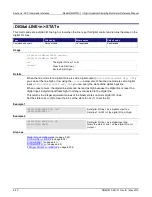
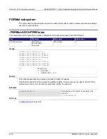
Details
Function
Default value
Range
Voltage (AC and DC)
60 Hz: 16.67 ms
50 Hz: 20 ms
8.333
µ
s to 0.25 s
10
µ
s to 0.24 s
Current (AC and DC)
60 Hz: 16.67 ms
50 Hz: 20 ms
8.333
µ
s to 0.25 s
10
µ
s to 0.24 s
Resistance (2-wire and 4-wire)
60 Hz: 16.67 ms
50 Hz: 20 ms
8.333
µ
s to 0.25 s
10
µ
s to 0.24 s
Diode
60 Hz: 16.67 ms
50 Hz: 20 ms
8.333
µ
s to 0.25 s
10
µ
s to 0.24 s
Temperature
60 Hz: 16.67 ms
50 Hz: 20 ms
8.333
µ
s to 0.25 s
10
µ
s to 0.24 s
Frequency and Period
10 ms
10 ms to 0.273 s
Voltage ratio
60 Hz: 16.67 ms
50 Hz: 20 ms
8.333
µ
s to 0.25 s
10
µ
s to 0.24 s
Digitize (voltage and current)
Automatic
1
µ
s to 1 ms set in 1
µ
s increments
The functionality of aperture depends on whether you are using a measure function or a digitize
function.
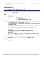
Aperture for a measure function
If you are using a measure function, the aperture sets the amount of time the ADC takes when
making a measurement, which is the integration period for the selected measurement function. The
integration period is specified in seconds. In general, a short integration period provides a fast
reading rate, while a long integration period provides better accuracy. The selected integration period
is a compromise between speed and accuracy.
During the integration period, if an external trigger with a count of 1 is sent, the trigger is ignored. If
the count is set to more than 1, the first reading is initialized by this trigger. Subsequent readings
occur as rapidly as the instrument can make them. If a trigger occurs during the group measurement,
the trigger is latched and another group of measurements with the same count will be triggered after
the current group completes.
You can also set the integration rate by setting the number of power line cycles (NPLCs). Changing
the NPLC value changes the aperture time and changing the aperture time changes the NPLC value.
To calculate the aperture based on the NPLC value, use the following formula.
where:
•
Aperture is the integration rate in seconds for each integration
•
NPLC is the number of power line cycles for each integration
•
f is the power line frequency