


DAQ6510 Data Acquisition / Multimeter System User's Manual
Section 6: Scanning low-level DCV
DAQ6510-900-01Rev. A / April 2018
6-3
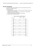
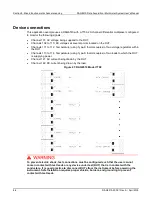
4. Connect six devices.
5. Route the cables out through the cable channels and secure the top cover.
6. Ensure that the DAQ6510 power is turned off.
7. Insert the 7700 into a slot on the rear of the DAQ6510.
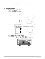
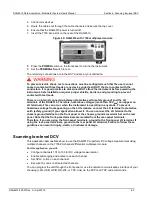
Figure 39: DAQ6510 with 7700 multiplexer module
8. Press the
POWER
switch on the front panel to turn on the instrument.
9. Set the
TERMINALS
switch to rear.
The remaining connections are to the DUT and are at your discretion.
To prevent electric shock, test connections must be configured such that the user cannot
come in contact with test leads or any device under test (DUT) that is in contact with the
conductors. It is good practice to disconnect DUTs from the instrument before powering the
instrument. Safe installation requires proper shields, barriers, and grounding to prevent
contact with test leads.
There is no internal connection between protective earth (safety ground) and the LO
terminals of the DAQ6510. Therefore, hazardous voltages (more than 30 V
RMS
) can appear on
LO terminals. This can occur when the instrument is operating in any mode. To prevent
hazardous voltage from appearing on the LO terminals, connect the LO terminal to protective
earth (safety ground) if your application allows it. You can connect the LO terminal to the
chassis ground terminal on the front panel or the chassis ground screw terminal on the rear
panel. Note that the front-panel terminals are isolated from the rear-panel terminals.
Therefore, if you are using the front-panel terminals, ground to the front-panel LO terminal. If
using the rear-panel terminals, ground to the rear panel LO terminal. Failure to follow these
guidelines can result in injury, death, or instrument damage.
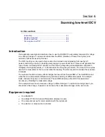
Scanning low-level DCV
This application demonstrates how to use the DAQ6510 to perform DC voltage measurement using
multiple channels on the 7700 20-channel differential multiplexer module.
For this application, you will:
•
Configure channels 101 to 106 for DC voltage measurement.
•
Enable autoranging and autozero on each channel.
•
Set NPLC to five on each channel.
•
Execute 10 scans on all selected channels.
You can program the unit through the front panel or use the remote communications interface of your
choosing (LAN, USB, GPIB, RS-232, or TSP-Link) via the SCPI and TSP code commands.