


Limit Testing
11-15
Con
fi
guring and performing limit tests
Con
fi
guring limit tests
Press CONFIG and then LIMITS to display the CONFIG LIMITS MENU. The limits con-
fi
guration menu is structured shown below and in Figure 11-10. The limits con
fi
guration menu
is structured as follows. Note that bullets indicate the primary items of the limit menu and
dashes indicate the options of each menu item. Refer to Section 1,
Rules to navigate menus
to
con
fi
gure the limit tests.
•
DIGOUT
—
Use this menu item to control the following Digital I/O aspects:
-
SIZE
—
Use to select 3-BIT or 4-BIT Digital I/O bit size (or 16-BIT with 2499-
DIGIO opion). In the 3-BIT mode, Digital I/O line 4 becomes the EOT, /EOT,
BUSY, or /BUSY signal depending on the selected END OF TEST mode. In the 4-
BITmode, Digital I/O line 4 is controlled manually if the END OF TEST mode is
set to EOT.
-
MODE
—
Use to select GRADING or SORTING mode. In GRADING mode, a
reading passes if it is within all of the HI/LO limit tolerances enabled, assuming
that it has passed the Compliance tests
fi
rst. The Digital I/O will be driven with the
fi
rst pattern of the
fi
rst Compliance, HI, or LO failure. Otherwise, the pass pattern
will be output. In GRADING mode, you will also choose bin control modes. With
IMMEDIATE, the testing process will stop after the
fi
rst failure and place the fail
pattern on the digital output. If none of the limit tests fail, the pass pattern will be
placed on the output, and the testing process will stop. With END, the testing pro-
cess will continue until the programmed sweep is completed, regardless of how
many failures occur. This allows multi-element devices (i.e., resistor networks) to
be tested. After testing is
fi
nished, the bit pattern for the
fi
rst failure is placed on
the output. If all tests pass, the pass pattern will instead be placed on the output.
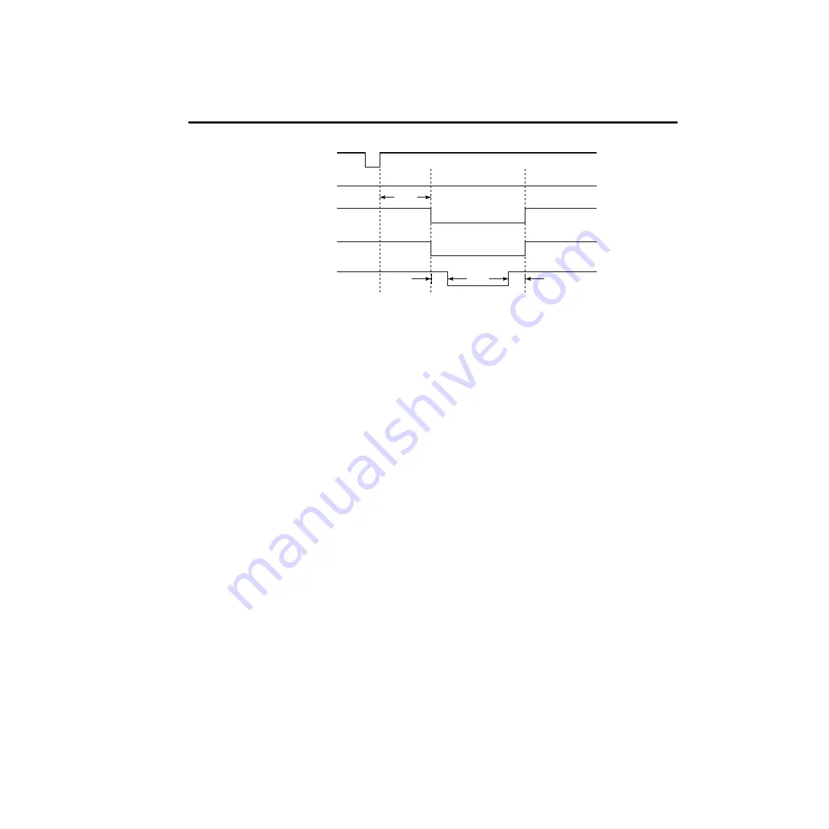
SOT*
Line 1
Line 2
Line 3
Line 4
/EOT (3-bit mode)
10
µ
s
10
µ
s
Delay
* With the SOT line being pulsed low (as shown),
⇓
STEST must be the selected arm
event for the trigger model. If the SOT line is instead pulsed high by the handler,
⇑
STEST must be the selected arm event.
Meas.
Figure 11-9
Digital output
auto-clear timing
example
Summary of Contents for 6430
Page 26: ......
Page 32: ......
Page 78: ...2 14 Connections ...
Page 98: ...3 20 Basic Source Measure Operation ...
Page 138: ...5 30 Source Measure Concepts ...
Page 156: ...6 18 Range Digits Speed and Filters ...
Page 168: ...7 12 Relative and Math ...
Page 176: ...8 8 Data Store ...
Page 202: ...9 26 Sweep Operation ...
Page 248: ...11 22 Limit Testing ...
Page 310: ...16 6 SCPI Signal Oriented Measurement Commands ...
Page 418: ...17 108 SCPI Command Reference ...
Page 450: ...18 32 Performance Verification ...
Page 477: ...A Specifications ...
Page 489: ...B StatusandErrorMessages ...
Page 498: ...B 10 Status and Error Messages ...
Page 499: ...C DataFlow ...
Page 503: ...D IEEE 488BusOverview ...
Page 518: ...D 16 IEEE 488 Bus Overview ...
Page 519: ...E IEEE 488andSCPI ConformanceInformation ...
Page 523: ...F MeasurementConsiderations ...
Page 539: ...G GPIB488 1Protocol ...
Page 557: ......


