5-6
Delta, Pulse Delta, and Differential Conductance
Model 6220/6221 User’s Manual
Return to
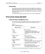
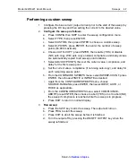
Trigger Link
– The Trigger Link synchronizes triggering between the Current
Source and the Nanovoltmeter. Trigger Link connections assume that the Model
2182/2182A is using the factory default (hard-wired) configuration:
EXT TRIG (input) = line #2
VMC (output) = line #1)
Delta, Pulse Delta, and Differential Conductance will not work if the
Model 2182/2182A is not using the default Trigger Link configuration. See
“Changing trigger link lines” in Section 5 (Disassembly) of the Model 2182/2182A
Service Manual.
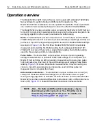
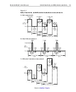
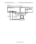
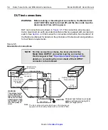
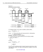
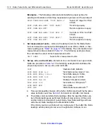
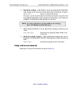
Figure 5-3
System connections – stand-alone operation
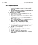
Connections – PC control system
System connections for this configuration are shown in
RS-232 and Trigger Link
– This system configuration uses the same RS-232 and
Trigger Link connections that are used for stand-alone operation.
IEEE-488 or Ethernet (6221)
– This system configuration uses a PC to communi-
cate with the Model 622x. For the Model 6220, the IEEE-488 bus interface can be
used. For the Model 6221, the IEEE-488 bus or the Ethernet can be used. For the
Ethernet, make sure to use a cross-over Ethernet cable for direct connection to
the PC.
ETHERNET
iEEE-488
RS-232
TRIGGER LINK
RS-232
iEEE-488
TRIGGER
LINK
(null-modem, male-to-male)
8501 Trigger Link Cable
Keithley 622x Current Source
Keithley 2182/2182A Nanovoltmeter
RS-232 Cable
Summary of Contents for 6220 DC
Page 2: ......
Page 4: ......
Page 6: ......
Page 16: ......
Page 36: ...1 20 Getting Started Model 6220 6221 User s Manual Return to Section 1 topics...
Page 131: ...6 10 Averaging Filter Math and Buffer Model 6220 6221 User s Manual Return to Section 6 topics...
Page 148: ...A Specifications...
Page 167: ......
Page 169: ......
Page 170: ......