T-GPS User Manual Version 1.2 | 9
3.2
Rear Panel
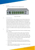
Figure 3.2 shows the detailed layout of a fully configured rear panel.
Figure 3.2: Rear Panel
3.3
Module Configuration
The rear panel shows the module configuration, which has 10 blank module positions.
The modules include Power, Outputs and Signal Input (Antenna). The Power Module and
Signal Input (Antenna) Module are mandatory. The different types of output module are
categorised into 7 different types including; dry contact output, TTL output, 485/422 output,
serial output, IRIG-B AC output, DCF77 output and Ethernet output. The dimensions of the
modules are the same, with the exception of the power Module which is installed on
the far left of the rear panel. The others can be installed anywhere on the rear panel.
Customers can order different modules according to their specific application requirements.
3.4
Outputs
There are different signal outputs for different modules which can be changed by changing
jumper or terminals.
•
Pulse x 4 includes A, B, C and D groups. These four pulses can be set from the front
panel as 1 pulse per hour (1PPH), 1 pulse per 30 minutes (1PP30M), 1 pulse per 10
minutes 1PP10M, 1 pulse per minute (1PPM), 1 pulse per 30 seconds (1PP30S), 1 pulse
per 10 seconds (1PP10S), 1 pulse per second (1PPS), and event. For the detailed setting
method, refer to Section 7.3 Front Panel Setting. The pulse has three kinds of outputs,
Dry Contact Output, TTL Outputs, and Differential Outputs.
•
Serial Port: this provides TXD0 and TXD1 signals. The user can find the signal format
from
Section 7.4 Serial Port Output, and the output format from Section 4.7 Serial Port
Output Module.
•
IRIG-B Code: this includes IRIG-B DC and IRIG-B AC codes. IRIG-B DC code can be output
from the TTL Output or the Differential Output.


