T-GPS User Manual Version 1.2 | 20
4.14
IRIG-B Optical Input Module I
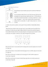
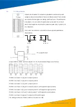
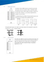
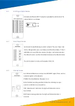
Each module has inputs for two IRIG-B optical signals (used for GPS
extension time synchronisation) and can indicate whether the optical
signals are connected and operating normally. There are four
indicators on the panel, from top to bottom: IRIG-B1, RUN1, IRIG-B2
and RUN2.
IRIG-B1 indicates whether the first optical signal input is present and
RUN1 indicates that it is operating normally. Under normal
conditions, IRIG-B1 flashes quickly and RUN1 flashes more slowly.
IRIG-B2 and Run2 have the same function for the second optical
signal input.
4.15
IRIG-B Optical Input Module II
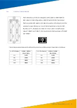
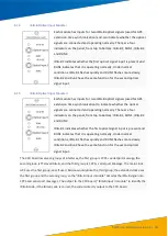
Each module has inputs for two IRIG-B optical signals (used for GPS
extension time synchronisation) to indicate whether the optical
signals are connected and operating normally. There are four
indicators on the panel, from top to bottom: IRIG-B1, RUN1, IRIG-B2
and RUN2.
IRIG-B1 indicates whether the first optical signal input is present and
RUN1 indicates that it is operating normally. Under normal
conditions, IRIG-B1 flashes quickly and RUN1 flashes more slowly.
IRIG-B2 and Run2 have the same function for the second optical
signal input.
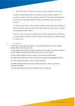
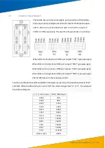
The CPU board reserves 3 groups of interfaces, the first group is 1PPS + serial port message, the
second group is TTL level IRIG-B, and the third group is 1PPS + serial port Message. The main clock
GPS uses the first group, and, if used, Beidou would utilise the third group; the extended clock uses
the first group and the second group, so the "IRIG-B input I module" decodes the IRIG-B signal into
1PPS and serial port messages. The output to the CPU board, "IRIG-B input II module" to identify the
IRIG-B code, if the IRIG-B code is correct, the code is directly output to the CPU board.

