Product overview
© KEB, 2008-02
COMBIVERT R6-S
Page 1.2 - 3
1
10
1.2 Product overview
1.2.1 Preface
First we would like to welcome you as a customer of the company Karl E. Brinkmann GmbH and congratulation
to the purchase of this product. You have decided for a product on highest technical level.
The enclosed documents as well as the specified hard- and software are developments of the Karl E. Brinkmann
GmbH. Errors excepted. The Karl E. Brinkmann GmbH has created these documents, this hard- and software
with the best knowledge. We doesn´t accept the guarantee that the user gets the profit with this specifications.
The Karl E. Brinkmann GmbH reserves the right to change specifications without prior notice or to instruct third
persons. This list is not exhaustive.
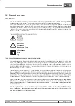
The used pictograms have following significance:
Danger
Warning
Caution
Attention
Essential
Discharge Time
Information
Help
Tip
1.2.2 Use of power supply and regenerative units
In power transmission different operating conditions occur with the electrical machines. Beside the motor ope-
ration, there is the regenerative operation, where energy is regenerate into the system. An inverter with uncon-
trolled rectifier enables only one energy flow direction, so usually the regenerative energy is dissipated with a
brake transistor and braking resistor. The overvoltage is limited by this way and thus an error disconnection or
destruction of the inverter is avoided.
The target of the regenerative unit is not to dissipate the regenerative energy into heat, but to regenerate the
usable energy into the net. Condition for this: inverters with at least one DC voltage
output, where the DC link
voltage is coupled to the regenerative unit. In this case decoupling diodes are used for determination of the energy
flow direction. The regenerative unit is connected via commutation throttle or harmonic filter and HF-filter with the
3-phase line. Thus a regenerative unit is place-, energy-saving, environmentally friendly and cost reducing.
If several inverters are used in a machine, these can be coupled via DC interconnection with the regenerative
unit, whereby the DC link voltage becomes more stable within the interconnection. This can improve the proces-
sing of the individual drives. To make the wiring as simple as possible, it is reasonable to supply the inverters
via DC interconnection.
Here the regenerative unit serves simultaneously as supply unit. The inverters must be designed for DC voltage
supply in this case. The COMBIVERT R6-S power supply and regenerative units can be parallel connected for
high power supply and/or regenerative supply.
Summary of Contents for combivert R6-S
Page 1: ...APPLICATION MANUAL Mat No Rev 00R6SEA K130 1 A GB KEB COMBIVERT R6 S Version 1 3 ...
Page 2: ...Page 1 1 2 COMBIVERT R6 S KEB 2008 02 Introduction ...
Page 4: ...Page 1 1 4 COMBIVERT R6 S KEB 2008 02 Introduction ...
Page 14: ...Page 1 2 6 COMBIVERT R6 S KEB 2008 02 Product overview ...
Page 28: ...Page 2 1 6 COMBIVERT R6 S KEB 2008 02 Fundamentals ...
Page 34: ...Page 2 2 6 COMBIVERT R6 S KEB 2008 02 Password structure ...
Page 116: ...Page 3 8 2 COMBIVERT R6 S KEB 2008 02 Special functions 3 8 1 Program timer counter 3 8 3 ...
Page 130: ...Page 3 9 10 COMBIVERT R6 S KEB 2008 02 Define CP Parameters ...
Page 140: ...Page4 2 2 COMBIVERT R6 S KEB 2008 02 Start up ...
Page 144: ...Page4 2 6 COMBIVERT R6 S KEB 2008 02 Start up ...
Page 150: ...Page 5 1 6 COMBIVERT R6 S KEB 2008 02 Error assistance ...
Page 158: ...Page 6 1 8 COMBIVERT R6 S KEB 2008 02 Project design ...
Page 160: ...Seite 7 1 2 COMBIVERT R6 S KEB 2008 02 Annex 7 1 1 Keyword index 7 1 3 ...
Page 166: ......
Page 167: ......


