KEB COMBINORM B Instructions For Use Manual Download Page 37

37

 TrOUBLESHOOTING

8  Troubleshooting

The following table shows some causes and solutions of malfunctions during brake op-

eration. If this does not solve the problem or if other malfunctions occur, please contact 

our service department.
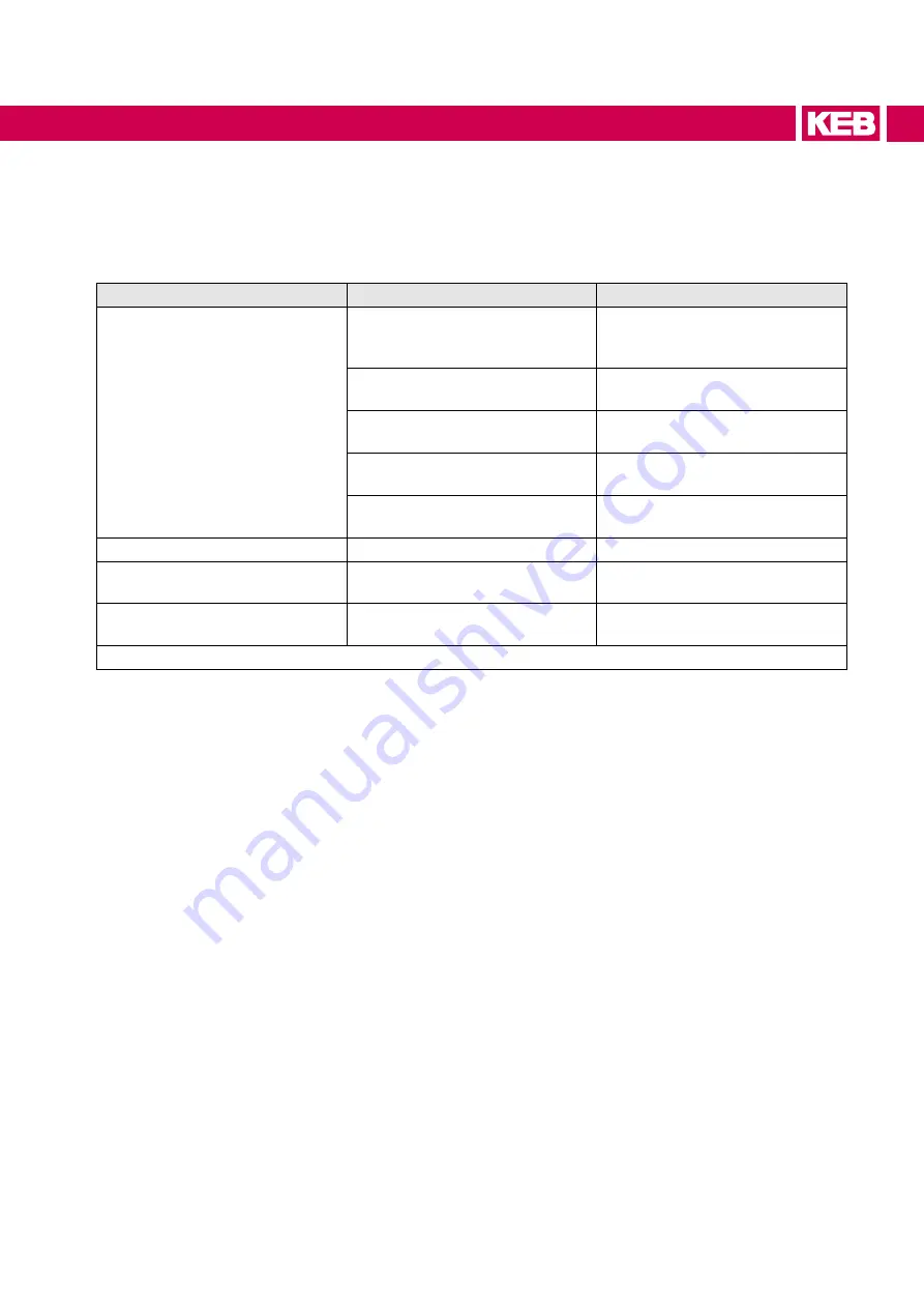
Malfunction

cause

Measures

Brake does not close

Incorrect voltage

Only operate the brake with the 

correct voltage  

(=> Magnet marking )

Air gap too large, maximum air 

gap reached

Replace the brake

Foreign objects between armature 

and magnet

Remove the foreign objects

Magnet coil or connecting cable 

defective

Replace the magnet

Excessive heating

Install a high-speed circuit breaker 

(for example, KEB Powerbox)

No braking function

Friction surfaces contaminated

Replace the brake

Brake does not open

Foreign objects between hub and 

armature

Remove the foreign objects

Brake engages with delay, long 

delay time

Brake is switched on the AC side

Switch the brake on DC side

Table 9: 

Troubleshooting

Summary of Contents for COMBINORM B

Page 1: ...COMBINORM TYPE B INSTRUCTIONS FOR USE INSTALLATION Translation of the original manual Document 20229885 EN 02...

Page 2: ......

Page 3: ...case of non observance of this safety instruction WARNING Dangerous situation which may cause death or serious injury in case of non observance of this safety instruction CAUTION Dangerous situation...

Page 4: ...s is outside of our control and therefore lies exclusively in the area of responsibility of the customer The information contained in the technical documentation as well as any user specific advice in...

Page 5: ...15 2 1 Intended use 15 2 2 Residual risks 15 2 3 Improper use 15 2 4 Type code COMBINORM Type B 16 2 5 Type code magnet 16 2 6 Overview COMBINORM Type B 17 2 6 1 Version 110 Flange mounted armature e...

Page 6: ...ghtening torque of the threaded pins 32 5 Electrical Connection 33 5 1 Connection of the brake 33 6 Start up 34 6 1 Inspections prior to start up of the brake 34 6 1 1 Visual inspection 34 6 1 2 Load...

Page 7: ...7 Table of Contents 12 Revision History 47...

Page 8: ...Figure 11 Example 2 Brake with armature element hub neck inside e g 01 12 02 120 xxxx 30 Figure 12 Example 3 Brake with armature element hub neck outside e g 01 12 02 130 xxxx 31 Figure 13 Mounting w...

Page 9: ...Reference potential ground Manufacturer The manufacturer is KEB unless oth erwise specified e g as a manufac turer of machines motors vehicles or adhesives IEC International standard IP xx Degree of p...

Page 10: ...nmental parameters and their severities Section 1 Storage IEC 104 648 CD EN60721 3 2 Classification of environmental conditions Part 3 Classification of groups of environmental parameters and their se...

Page 11: ...eration and maintenance of the prod uct Understanding of the function in the used machine Detection of hazards and risks of the drive technology Knowledge about work safety and accident prevention e g...

Page 12: ...otation Consider the following installation measures to prevent faults Do not operate the brake in an explosive environment Provide measures against freezing or ice formation on the friction surfaces...

Page 13: ...nction unusual noises or smells inform a person in charge DANGER Unauthorized exchange repair and modifications Unpredictable malfunctions The brake must not be converted modified or misused Only use...

Page 14: ...or the return point can be found in the list below Shipping costs will be borne by the customer Thereupon the devices will be professionally recycled and disposed The entry numbers are listed country...

Page 15: ...tructions for use and must be strictly observed Any use beyond the technical specifications is also considered as not specified The actual use of the brake in the target products is beyond KEB Automat...

Page 16: ...plete material number is not printed on the brake Only the magnet is marked with a material number An assignment of the brake based on the magnet marking is only possible to a limited extent 2 5 Type...

Page 17: ...2 2 1 6 3 6 2 1 4 Legend 1 1 Magnet 2 1 Socket screws e g ISO 4762 2 2 Socket screws e g ISO 6912 3 Mounting surface e g motor 4 Schnorr lock washers 6 Mounting surface evaluated by the customer e g b...

Page 18: ...ement with internal hub 5 3 1 1 6 2 7 2 1 4 Legend 1 1 Magnet 2 1 Socket screws e g ISO 4762 3 Mounting surface e g motor 4 Feather key 5 Shaft 6 2 Armature element hub neck inside 7 Locking ring Figu...

Page 19: ...ement with external hub 1 1 5 8 4 6 3 3 2 1 Legend 1 1 Magnet 2 1 Socket screws e g ISO 4762 3 Mounting surface e g motor 4 Feather key 5 Shaft 6 3 Armature element hub neck outside 8 Threaded pin Fig...

Page 20: ...Version 320 Shaft mounted 4 5 1 2 2 1 8 3 6 4 Legend 1 2 Magnet 2 1 Socket screws e g ISO 4762 3 Mounting surface e g motor 4 Feather key 5 Shaft 6 4 Armature element for brake 8 Threaded pin Figure...

Page 21: ...ld is used to build up torque The armature disk is attracted to the brake magnet and the torque is transmitted by a diaphragm spring without torsional backlash and without wear After switching off the...

Page 22: ...3 1 Operating conditions 3 1 1 Electrical operating conditions 3 1 1 1 Device classification Requirement Standard Class Notes Overvoltage category EN 60664 1 III Table 3 Device classification 22 Oper...

Page 23: ...0 021 0 068 0 18 0 53 1 57 5 29 15 1 50 1 159 437 Mass moment of inertia Armature element B 320 J 10 4 kgm 0 82 2 6 10 3 27 101 Nominal air gap X mm 0 1 0 15 0 15 0 2 0 2 0 2 0 2 0 3 0 3 0 4 0 4 Air g...

Page 24: ...5 23 30 38 50 60 76 95 120 158 210 G 2x2 1 3x2 6 3x3 1 3x3 1 3x4 1 3x4 1 3x5 1 3x6 1 3x8 1 3x10 1 4x12 1 H 5 3 6 6 6 5 10 11 11 5 15 21 19 28 J 4 5 5 5 5 5 5 8 8 10 11 5 14 5 17 5 20 5 K 3 3 3 2 3 5 4...

Page 25: ...0 02 320 xxxx Size Dimensions mm A B D N4 01 03 P6 R5 S4 U W4 X Z d4 d5 Weight kg 02 320 06 80 72 63 31 2 3 19 9 3 6 3 45 39 M4 0 2 M6 20 18 0 8 07 100 90 80 34 2 3 21 5 13 2 6 9 52 5 45 M5 0 2 M8 22...

Page 26: ...when the supply voltage is disconnected to avoid overexpansion of the diaphragm spring at the armature element Magnet and armature element must be centered at mounted brakes Axial and radial run out...

Page 27: ...lange 2 Magnet 3 Armature element 4 Customer shaft Size 01 02 03 05 06 07 08 09 10 k mm 0 1 0 1 0 1 0 1 0 2 0 2 0 2 0 2 0 3 r mm 0 04 0 04 0 04 0 06 0 06 0 06 0 06 0 08 0 08 Figure 8 Concentricity k b...

Page 28: ...rewed to the mounting surface with socket head screws e g DIN 4762 8 8 Inside centering e g 01 12 02 110 120 130 xxxx The magnet can be centered via the inside diam eter of the magnet and screwed to t...

Page 29: ...the air gap X can be adjusted with adjusting washers between armature element 6 1 and shaft Mount the magnet 1 1 with the socket head screws 2 1 to the mounting surface 3 Place the armature element 6...

Page 30: ...uring mounting the air gap X occurs automatically If necessary the air gap X can be adjusted with adjusting washers between armature element 6 2 and shaft 5 Mount the feather key 4 into the shaft 5 Mo...

Page 31: ...sary the air gap X can be adjusted with adjusting washers between armature element 6 3 and shaft 5 Mount the feather key 4 into the shaft 5 Mount the magnet 1 1 with the socket head screws 2 1 to the...

Page 32: ...cket head screws 2 1 to the mounting surface 3 If the magnet flange shall be used as torque arm the hub is pushed onto the motor shaft 5 with mount ed feather key 4 and secured axially on the shaft 5...

Page 33: ...of incorrect voltage supply The brake is operated with DC voltage Read the rated voltage from the magnet marking of the brake Compare with existing voltage source The maximum input voltage Uin must no...

Page 34: ...supply NOTICE Damage due to non observance Do not put into operation if one of the tests is not OK 6 1 3 Run in of the brake NOTICE Damage due to insufficient rated braking torque The rated braking t...

Page 35: ...t s 1 0 5 Speed n rpm 25 Switching cycles 20 15 Table 7 Function running in 6 1 3 2 Maintenance running in Application Brake recovery due to unfavorable operating conditions Device size 01 02 03 05 06...

Page 36: ...36 Operation 7 Operation The brake is only electrically controlled There are no manual operating options...

Page 37: ...ing Air gap too large maximum air gap reached Replace the brake Foreign objects between armature and magnet Remove the foreign objects Magnet coil or connecting cable defective Replace the magnet Exce...

Page 38: ...n the air gap X is checked at regular intervals 9 2 Service Service is required if in accordance with the fault table there are symptoms of damaged or soiled friction surfaces unusual noises or smells...

Page 39: ...llelism and axial run out tolerances must be added to the rated air gap X Size Air gap Rated value X Limit value Xn_max mm mm 01 0 1 0 3 02 0 15 0 35 03 0 15 0 35 05 0 2 0 5 06 0 2 0 6 07 0 2 0 7 08 0...

Page 40: ...ge the brake with armature element must be completely replaced Disconnect the connecting cable s from the voltage supply Dismount the brake 9 2 1 Dismount the brake The brake is assembled in reverse o...

Page 41: ...rake components in compliance with the applicable local environmental regulations The corresponding key numbers are subject to change depending on the disassembling process metals plastics and cables...

Page 42: ...es zur Angleichung der Rechtsvorschriften der Mitgliedsstaaten betreffend elektrischer Betriebsmittel zur Verwendung innerhalb bestimmter Spannungsgrenzen Number Gef hrliche Substanzen 2011 65 EU inkl...

Page 43: ...DE 0580 11 2011 Informativ EN Norm Text Referenz Ausgabe EN 50178 Ausgabe 1997 Ausr stung von Starkstromanlagen mit elektronischen Betriebsmitteln VDE 0160 04 1998 Die bereinstimmung des bezeichneten...

Page 44: ...CONTROL EQUIPMENT Miscellaneous Apparatus CLASS C321187 INDUSTRIAL CONTROL EQUIPMENT Miscellaneous Apparatus Certified to US Standards Spring Applied Brakes COMBISTOP open type 290 VDC de or less ins...

Page 45: ...TOP The following three figures describe the design and the last four figures describe the layout of the product type 2 Component magnets equipped with not certified leads are supplied with levels acc...

Page 46: ...05 Update of report to cover correction of issued address and to update report in accordance with CSA C22 2 No 14 18 and Certification notice Industrial Control Equipment No 60 dated at April 26 2018...

Page 47: ...47 Revision History 12 Revision History Version Date Description 01 2011 09 First edition 02 2021 06 Complete editorial revision change of cover picture content adjustments...

Page 48: ...48 NOTES...

Page 49: ...0074 Japan Tel 81 33 445 8515 Fax 81 33 445 8215 E Mail info keb jp Internet www keb jp MORE KEB PARTNERS WORLDWIDE www keb de contact contact worldwide P R China KEB Power Transmission Technology Sh...

Page 50: ...Automation with Drive www keb de KEB Automation KG Suedstrasse 38 32683 Barntrup Tel 49 5263 401 0 E Mail info keb de...

Reviews: