61
6
Panoramic and 3D calibrations and
adjustments
6.1 Introduction
The calibration procedure helps to maintain image quality
and correct operation of the unit.
When carrying out the full or partial calibration procedure,
the calibration and check steps must be carried out in the
order in which they are listed.
During the calibration procedure calibration data is
produced. This data, which is stored in the Touch screen
display PC and on the R3220, is used for unit calibration
and image processing. Resulting from the calibration
programs are also calibration images containing calibration
results, telling the operator how to proceed with the
calibration and adjustment procedure.
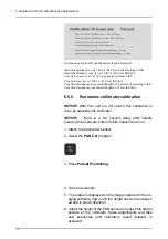
In addition to the calibration name (e.g. Adjustment
panCol) the images contain image data sampled during the
calibration, adjustment instructions and a “Passed / Not
Passed / Failed” calibration status.
-
Passed
means that the calibration program is suc-
cessfully done. Move on to next calibration.
-
Not passed
means that adjustment is still needed.
Follow the instructions the image (if any) and take
another exposure. Some calibration programs are
iterative and demand a few repetitions.
-
Failed
means that the system could not decide
what adjustment should be done in order for the
calibration to succeed. This calibration status is al-
ways the result of some error condition. Taking an-
other exposure will not help. The image may give a
hint on what the problem is (e.g. no radiation, colli-
mator severely tilted, image data corrupted…).
Contact service if the problem persists after restart-
ing the unit and PC.
NOTICE! Panoramic and 3D calibration images are shown
on the screen as viewed from the x-ray tube. All
adjustment instructions contained in the calibration images
also refers to this perspective.
NOTICE! There are exclamation marks displayed at each
calibration program key icon for programs that are yet not
Summary of Contents for ORTHOPANTOMOGRAPH OP 3D Pro
Page 2: ......
Page 4: ......
Page 8: ...iv rev...
Page 18: ...1 Introduction 10...
Page 27: ...2 Unit description 19 2 6 Unit movements Panoramic unit movements R C J D...
Page 29: ...2 Unit description 21...
Page 30: ...2 Unit description 22...
Page 38: ...4 PC requirements 30...
Page 54: ...5 Installing the unit 46 4 Fasten the covers...
Page 67: ...5 Installing the unit 59 C C D D Top cover of the column E E...
Page 104: ...7 Cephalometric calibration and alignment 96...
Page 111: ...7 Cephalometric calibration and alignment 103 3 Tighten the locking nut...
Page 117: ...7 Cephalometric calibration and alignment 109...
Page 128: ...8 Special procedures 120 6 Remove the arm from the column 4 nuts 7 Disassemble the arm...
Page 132: ...8 Special procedures 124 right handed assembly Prism assembly for the left handed cephalostat...
Page 158: ...8 Special procedures 150...
Page 165: ...9 OP 3D Pro Pre sales check list 157 9 11 Notes comments...
Page 166: ...9 OP 3D Pro Pre sales check list 158 9 12 Dimensions 463...
Page 167: ...9 OP 3D Pro Pre sales check list 159 9 13 Dimensions with cephalostat...

