8 Special procedures
142
8.
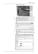
Mark the Program/Configure check box.
9.
Click the Start button and wait for the download to com-
plete (takes a few seconds).
10. Volatile installation is typically followed by a permanent
install. Refer to chapter Manual update for instructions
on how to do this. The volatile install is voided if the unit
is powered off before the software is permanently in-
stalled.
8.9 Special cases
8.9.1
Programming a R3220 Main CPU
board having wrong unit type
configured
In case the CPU board is configured with wrong unit type
or does not have a unit type configured, the s2terminal will
not be able to locate the programming files properly. This is
possible, for example, if a spare part R3220 board is used.
To decide the unit type assumed by the s2terminal, follow
the messages printed in the prompt right after a connection
has been established.
If the board's unit type is not recognized by the s2terminal,
it will prompt the user for the type to use. Enter the unit's
type and program the board according to the instructions in
chapter 8.7.2.2 Manual update.
If the board's unit type is not what it should be,
programming must be done using an explicitly named
programming file. See instructions below.
To program a R3220 Main CPU board using explicitly
named programming files:
1.
Establish a connection to the board as per instructions
in Preparing for update.
2.
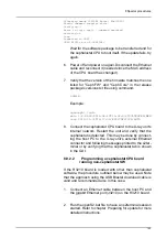
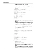
Update the FGPA core using the command:
xcpr 3220 OP3DPRO_R3220_R<ver_ma-
jor>_<ver_minor>.pof
Example:
xcp r3220 OP3DPRO_R3220_R2_00.pof
Wait until the software is transferred and power off the
unit.
Summary of Contents for ORTHOPANTOMOGRAPH OP 3D Pro
Page 2: ......
Page 4: ......
Page 8: ...iv rev...
Page 18: ...1 Introduction 10...
Page 27: ...2 Unit description 19 2 6 Unit movements Panoramic unit movements R C J D...
Page 29: ...2 Unit description 21...
Page 30: ...2 Unit description 22...
Page 38: ...4 PC requirements 30...
Page 54: ...5 Installing the unit 46 4 Fasten the covers...
Page 67: ...5 Installing the unit 59 C C D D Top cover of the column E E...
Page 104: ...7 Cephalometric calibration and alignment 96...
Page 111: ...7 Cephalometric calibration and alignment 103 3 Tighten the locking nut...
Page 117: ...7 Cephalometric calibration and alignment 109...
Page 128: ...8 Special procedures 120 6 Remove the arm from the column 4 nuts 7 Disassemble the arm...
Page 132: ...8 Special procedures 124 right handed assembly Prism assembly for the left handed cephalostat...
Page 158: ...8 Special procedures 150...
Page 165: ...9 OP 3D Pro Pre sales check list 157 9 11 Notes comments...
Page 166: ...9 OP 3D Pro Pre sales check list 158 9 12 Dimensions 463...
Page 167: ...9 OP 3D Pro Pre sales check list 159 9 13 Dimensions with cephalostat...


