1 Introduction
6
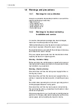
1.6.3
Cautions for Electrostatic discharge
1.6.4
General warnings
Electrostatic Discharge (ESD) can damage or destroy elec-
tronic components.
When servicing the device take precautions to avoid elec-
trostatic build up and discharge (ESD). Follow the recom-
mendations for the prevention of ESD that are used in the
country in which you are working. If no recommendations
are available follow the guide lines below.
Leave all new or replacement circuit boards and electrical
parts in their protective packaging until the boards are
needed.
Before handling circuit boards and electrical parts make
sure that any static electricity charge that has built up in you
body is discharged.
When handling circuit boards hold them by their edges and
do not touch any connectors or components.
When examining and checking circuit boards use an elasti-
cated wrist wrap which is connected to a ground point
through a 1 Mohm current limiting cable. For a ground point
use water pipes, radiators or other objects that are known
to be connected to the ground. Also use a cable to connect
the x-ray unit to the same ground potential as the wrist
wrap.
If an antistatic mat is used, connect the wrist wrap to the mat
and the mat to the ground potential.
Wash the wrist wrap and check that it is in good condition
frequently.
Personnel operating the device must be adequately trained
with respect to the technological principles of operation and
radiation protection when using cone beam computed
tomography (CBCT) imaging.
This unit complies with the EMC (Electromagnetic
Compatibility) according to IEC 60601-1-2. Radio
transmitting equipment, cellular phones etc. shall not be
used in close proximity of the unit as they could influence
the performance of the unit.
Summary of Contents for ORTHOPANTOMOGRAPH OP 3D Pro
Page 2: ......
Page 4: ......
Page 8: ...iv rev...
Page 18: ...1 Introduction 10...
Page 27: ...2 Unit description 19 2 6 Unit movements Panoramic unit movements R C J D...
Page 29: ...2 Unit description 21...
Page 30: ...2 Unit description 22...
Page 38: ...4 PC requirements 30...
Page 54: ...5 Installing the unit 46 4 Fasten the covers...
Page 67: ...5 Installing the unit 59 C C D D Top cover of the column E E...
Page 104: ...7 Cephalometric calibration and alignment 96...
Page 111: ...7 Cephalometric calibration and alignment 103 3 Tighten the locking nut...
Page 117: ...7 Cephalometric calibration and alignment 109...
Page 128: ...8 Special procedures 120 6 Remove the arm from the column 4 nuts 7 Disassemble the arm...
Page 132: ...8 Special procedures 124 right handed assembly Prism assembly for the left handed cephalostat...
Page 158: ...8 Special procedures 150...
Page 165: ...9 OP 3D Pro Pre sales check list 157 9 11 Notes comments...
Page 166: ...9 OP 3D Pro Pre sales check list 158 9 12 Dimensions 463...
Page 167: ...9 OP 3D Pro Pre sales check list 159 9 13 Dimensions with cephalostat...

