background image

13 of 56

5.1.3  Selecting the Installation Location

Essentially, the cable lengths and components that are supplied allow you a free choice of installation location on your 
caravan or motor home.

When selecting the installation location, take note of the following points:


Before installation, find out whether the operating manual for your vehicle permits the fitting of non-vehicle-specific 
parts or what requirements need to be met in order to do so.


For direct satellite reception, there should be no obstructions between the antenna and the satellite. Therefore, 
make sure that the antenna is not shadowed by roof attachments such as luggage racks, air conditioning units, solar 
panels, etc.


The problem of shadowing applies also when selecting a parking place for your vehicle. For interference-free satellite 
reception, the antenna needs a free view to the south at an angle of between 0° and 75° (depending on location) to 
the horizontal.


When selecting the installation location, take into account the range of movement of the turntable, see Chapter 
10, p. 35. There must not be any attachments on the roof that would obstruct this range of movement (risk of colli-
sion). To be on the safe side, keep slightly more than the required area free. This allows for an easier installation and 
any subsequent dismantling.


Choose an installation position on the roof that is as horizontal as possible or only slightly sloping, depending on the 
location of the vehicle, since roof inclinations greater than 5° may lead to problems when searching for the satellite.


To ensure secure adhesion, the height difference of the roof curve must not be more than 1 cm over a length of 2 m, 
as otherwise the gap between the roof and the mounting plate would be too great to be filled by the adhesive sealant.


As the vehicle is constantly subjected to vibration loads during travel, the roof below the antenna unit is also subject 
to significant loads. Please note, given the nature and capacity of your vehicle roof, that the weight of the antenna 
unit is approx. 9.7 kg, see the operating manual for the vehicle. In case of doubt, consult a qualified specialist dealer 
or your vehicle’s manufacturer.


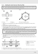
The roof duct provides a watertight seal through which the three cables (2 x coaxial cables, one power supply cable) 
are fed into the interior of the vehicle directly underneath the turntable. If you prefer a different method of laying the 
cables, you can run them out from the rear of the turntable via the channel provided in the mounting plate. The cables 
must then be run along the roof of the vehicle in a protective cable duct and through a separate roof duct HDZ 100 
(neither of them are included in the scope of delivery).


The HDZ 100 roof duct is available as an accessory under part number 20410032 from specialist dealers.

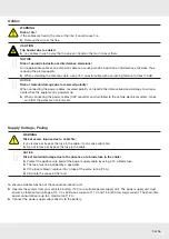
NOTICE
Risk of malfunction or material damage, in particular due to the absence of a blade fuse in the cable!


Protect the positive wire (red) of the power supply cable by using a 15 A blade fuse.


The fuse must be installed by a specialist.


If the fuse is blown, replace it by a fuse of the same rating (15 A).


Eliminate the cause of the fault.
Summary of Contents for MobiSet 3 Twin CAP 650

Page 1: ...MobiSet 3 Twin CAP 650 Translation of the original operating manual CAP 650 English IMPORTANT Read carefully before use...

Page 2: ...ons for Installation 22 5 2 4 Installing the CAP Converter on a TV Set 23 5 2 5 Installing the CAP Converter 24 5 2 6 Laying the Cables and Connecting the Turntable 25 5 2 7 Connecting the CAP Convert...

Page 3: ...e Using the External Push button 49 13 4 1 Starting the Turntable 49 13 4 2 Moving the Turntable to the Park Position 49 13 4 3 Resetting the CAP System 49 13 5 Updating Software and Channel List 49 1...

Page 4: ...ersione italiana delle istruzioni di montaggio dalla nostra rappresentanza1 piu vicina della sua citt oppure scaricarla dalla nostra web site2 E Para obtener la versi n espa ola de nuestro manual de i...

Page 5: ...n cable 5 m F type female connector to F type male connector 1 x power supply extension cable 7 m for connection to the on board power supply incl blade type fuse 15 A roof duct with sealing gasket DE...

Page 6: ...alignment of the satellite dish to receiver digital satellite signals The turntable is designed for use on stationary caravans or motor homes Any use other than that specified above will invalidate th...

Page 7: ...sure that the roof and climbing aid are dry clean and non slip WARNING Risk of severe injuries due to moving parts especially risk of crushing Make sure that no one and in particular no children is in...

Page 8: ...of of the vehicle by adhesive and is secured by additional screws Note that the curing of the adhesive sealant is temperature dependent It reaches its full strength only after approxi mately 2 days NO...

Page 9: ...ter and turntable to the vehicle electrical system make sure that the poles are not reversed Supply Voltage Fusing WARNING Risk of severe injuries due to cable fire If you remove or bypass the fuse in...

Page 10: ...er supply and to the ignition Checks before Commencing a Journey Before commencing a journey always lower the antenna into the horizontal position park position If the antenna has collided with a fixe...

Page 11: ...a wireless hotspot function Using the external operating unit2 To change the satellite position press buttons to set the values Using a software update of the xml file with satellites created on the...

Page 12: ...ing and Preparing NOTICE Risk of material damage during transportation Never carry the turntable on the planar antenna Keep the turntable in its cardboard box for transport on to the vehicle roof Unpa...

Page 13: ...linations greater than 5 may lead to problems when searching for the satellite To ensure secure adhesion the height difference of the roof curve must not be more than 1 cm over a length of 2 m as othe...

Page 14: ...n clearance 880 mm Park position Roof rail Roof attachments may be mounted within the hatched area High neighbouring attachments on the roof may lead to shadowing Area min 690 mm within which equipmen...

Page 15: ...ircle Tip The size of the holes and the choice of fastening screws to be used not included in the scope of delivery depend on the type and thickness of the materials used in the roof structure If the...

Page 16: ...e the roof duct Fig A and apply the adhesive sealant evenly to the underside of the roof duct flange Place the roof duct in the drilled hole and press it firmly against the roof of the vehicle Apply t...

Page 17: ...ravel see Fig E Make sure not to step on the connectors or kink or crush the cables 3 Align the through holes on the turntable with the threaded holes on the mounting plate When lowering make sure tha...

Page 18: ...OTICE Risk of material damage due to pulling the cables from the turntable Do not try to pull the cables from the unit 2 Place the turntable carefully on the mounting plate Make sure that the through...

Page 19: ...KAsyl MS adhesive sealant to the spigot of the roof duct Insert the spigot into the hole and secure it from below with the knurled nut 3 Unscrew the screws x 6 10 AF from the mounting plate and remove...

Page 20: ...which means that you do not have to place it where it is visible Therefore you can fit the CAP converter out of sight in any location e g on cupboard walls side walls or the base of storage compartmen...

Page 21: ...unit monitors its own temperature in operation Continuous operation at temperatures higher than the recommended operating temperature can cause premature failure of the unit as a result of insufficien...

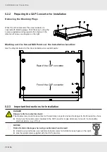
Page 22: ...etween screw drill points Rear of the CAP converter Fron of the CAP converter 5 2 3 Important Instructions for Installation DANGER Danger to life from electric shock The wood screws could make contact...

Page 23: ...k of a fatal electric shock Before starting any installation work disconnect all the units concerned from the mains Before installing the CAP converter on another electrical device check with the manu...

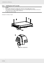
Page 24: ...l damage from applying too much force when tightening the screws If you apply too much force when tightening the screws you can damage the screw sockets and the CAP converter casing or any cables alre...

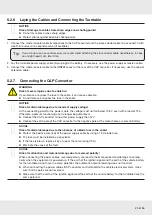
Page 25: ...oint for the power cable the voltage must not fall below 10 9 V even with a load of 12 A Otherwise optimum functioning can no longer be guaranteed Connect the CAP converter to no other power supply th...

Page 26: ...connecting cable marked IGNITION allows you to connect to a circuit in the vehicle that is activated when the ignition key is turned and then carries a continuous 12 V supply This type of connec tion...

Page 27: ...G Check the power rating of the circuit used with respect to the intended application 5 2 9 Connection Example for 12 V Battery Connection Fig G TV set 2 with a built in satellite tuner or satellite r...

Page 28: ...preferably align your antenna to the position of the ASTRA satellite 19 2 East picture below left EUTELSAT HOTBIRD 13 East picture below right The spots for these satellites are shown below The inner...

Page 29: ...6 screws which secure the turntable to the mounting plate 3 Place two wooden supports on the vehicle roof for protection 4 Place the turntable on the prepared wooden supports 5 Use the original packag...

Page 30: ...reception If required change the polarisation setting of the satellite antenna as follows 15 if the satellite is more than between 15 and 20 west of the preferred reception range 15 if the satellite i...

Page 31: ...ing operations Contact a technician or try to find a suitable person on the campsite 8 3 Setting Operations The following description assumes that the complete CAP unit has been properly assembled ins...

Page 32: ...crews to a torque of 6 7 Nm see in Fig J 6 Leave the installation location 7 Reconnect the CAP converter to the power supply 8 Switch the CAP converter on using the on off switch The system is ready f...

Page 33: ...sition yourself if you are unfamiliar with the necessary repair work Contact a technician or try to find a suitable person on the campsite It is necessary to recalibrate the antenna in an authorised w...

Page 34: ...as to free the rocker from the engagement on the tapered shaft Screw an M12 x 40 screw minimum length 22 mm into this thread The rocker is pushed off the taper seating on the tapered shaft and the eng...

Page 35: ...icle battery V 10 9 13 8 Power consumption from the 12 electrical system Inrush current Duration of the inrush current Satellite search TV reception Standby A ms A A mA typ 10 max 12 ca 200 typ 3 typ...

Page 36: ...36 of 56 Technical Data 10 2 Dimensions in mm 118 3 118 3 282 153 6 Mounting plate 145 66...

Page 37: ...37 of 56 Min recommended clearance 880 Rotary axis BAS 66 Roof duct Nut Clamping range 20 50 Mounting plate 145 146 incl mounting plate 211 701 248 400 10 323 442 38 17...

Page 38: ...oxications SECTION 2 Hazards identification 2 1 Classification of the substance or mixture Classification according to Regulation EC No 1272 2008 The product is not classified according to the CLP reg...

Page 39: ...for several minutes under running water If symptoms persist consult a doctor After swallowing Wash out mouth with water Contact a physician 4 2 Most important symptoms and effects both acute and dela...

Page 40: ...e monitored at the workplace CAS No Designation of material Type Value Unit Not required Additional information The lists valid during the making were used as basis 8 2 Exposure controls Personal prot...

Page 41: ...te Not determined Solubility in Miscibility with water Not miscible or difficult to mix Partition coefficient n octanol water Not determined Viscosity Dynamic Not determined Kinematic Not determined S...

Page 42: ...available Additional ecological information General notes Water hazard class 1 German Regulation Self assessment slightly hazardous for water Do not allow undiluted product or large quantities of it...

Page 43: ...has not been carried out SECTION 16 Other information This information is based on our present knowledge However this shall not constitute a guarantee for any specific product features and shall not...

Page 44: ...List of Notified Chemical Substances CAS Chemical Abstracts Service division of the American Chemical Society LC50 Lethal concentration 50 percent LD50 Lethal dose 50 percent Flam Liq 3 Flammable liqu...

Page 45: ...tal surfaces glass PVC polyester GRP painted and lacquered wood etc No adhesion on untreated polyethylene polypropylene and teflon In those cases where due to great thermal or physical loads especiall...

Page 46: ...SO 37 ca 210 Shear stress DIN 53283 ASTM D1002 ca 2 5 MPa Alu Alu adh thickness 2mm test speed 50 mm min Tear propagation DIN 53515 ISO 34 ca 14 N mm Type C test speed 500 mm min Solvent percentage 0...

Page 47: ...47 of 56...

Page 48: ...650 starts from this page If despite studying these operating instructions you still have questions about getting started with the unit or using it correctly or if unexpected problems occur please co...

Page 49: ...of malfunction and material damage from Overheating of the turntable motor If the turntable motor operates without interruption for longer than 20 minutes it can cause overheating of the motor None of...

Page 50: ...T socket NOTICE Risk of material damage Do not interchange the cables 2 Make sure that the supplied 12 V connection cable is installed by a specialist dealer 1 Not included in the scope of delivery DE...

Page 51: ...ing the on off switch 6 Switch the CAP converter back on The channel list is loaded when the CAP converter starts The LED status shows whether the channel list has been successfully downloaded or whet...

Page 52: ...CAP converter to operate normally again Normal operation Green LED flashes slowly CAP is in the park position LED flashes 3 x then stops for a bit CAP is moving to a position e g to the park position...

Page 53: ...AMENT AND THE COUNCIL dated 27th January 2003 concerning used electrical and electronic appliances it must be disposed of properly At the end of its service life take this unit for disposal at a desig...

Page 54: ...54 of 56 Declaration of Conformity 15 Declaration of Conformity...

Page 55: ...55 of 56...

Page 56: ...www kathrein com sat kathrein de KATHREIN Werke KG Anton Kathrein Stra e 1 3 83022 Rosenheim Germany Phone 49 8031 184 0 Fax 49 8031 184 52360 936 5022 VMPT 0116 GB Subject to change...

Reviews: