background image


Deutsch 

5.962-786.0 Rev. 05 (06/13)

 65

Detergent supply unit for central supply of cleaning 
systems with any number of access points.

The dosing centre is mostly set up operational and 
consists of a PE container for the stockage of the de-
tergent, the pump unit, the mixing unit and the switch 
cabinet for wall installation. The connecting hose with 
hose stem as well as the fastening material is includ-
ed in the scope of delivery.

For each extraction point the suitable injector and the 
ball valve are additionally required. Before each in-
jector and after each PE detergent tank these ball 
valves must be installed.

The dosing centre will be taken into operation togeth-
er with the high pressure supply. It is designed to sup-
ply several access points simultaneously. In the 
partial load area, the volume that has not been ex-
tracted will be routed back to the storage container 
via a dosing valve.

The pump unit is designed as a glandless diaphragm 
dosing pump with a separating chamber and manual 
adjustment. It is driven by an electric motor and a 
crank drive running in an oil bath.

Diaphragm casing made of PE RCH 500, diaphragm 
PTFE coated, valve made of PVC with ceramic balls, 
hypalon seal and connecting parts made of PVC en-
sure a high resistance over a wide pH range.

The connection between the supply unit and the ex-
traction point is ensured by means of an injector. This 
ensures the addition of the concentrated detergent 
directly at the extraction point. If two different deter-
gent are to be used for cleaning, the addition of the 
detergents is to be performed via a complete dosing 
unit, double (order no. 2.641-702.0). If only one de-
tergent is required, the standard injector for 1 deter-
gent can be used (order no. 3.637-001.0).

Note:
An injector must be installed at every extraction point 
at which work is performed with a detergent. See 
Chapter 7.6.4 for detailed information concerning the 
injectors used.

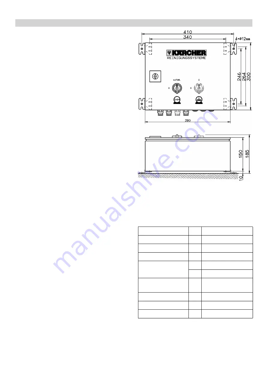
Switch cabinet dosing centre

The control is designed as a contactor control; the 
motor is monitored by a motor protection relay with a 
pre-fuse. The switch cabinet is set up as per the VDE 
guidelines and wired onto series terminals.

Technical data:

7.5

Accessories for central detergent supply

7.5.1

Supply unit of dosing centre

Pump capacity

l/h

208

Pressure

bar

max. 10 bar

Container capacity

l

2

00

Mixing unit

Hand mixer

Electrical connection V

3x400

Hz

50

Dimensions

mm Diameter

860x1750

Weight

kg

80

Power

kW

0,37

Order No.

3.910-005.0

Summary of Contents for HDC Series

Page 1: ...HDC Series Planning Manual 5 962 786 0 13 SWEEPEX AUSTRALIA 1800 680 337 www sweepex com au sales sweepex com au...

Page 2: ...sure side 16 3 2 5 Pressure regulation 16 3 2 6 Controls 16 3 3 Safety Devices 16 3 3 1 Safety mechanism against lack of water in swimmer tank 16 3 3 2 Temperature sensor 16 3 3 3 Winding protection c...

Page 3: ...Manual operation 32 4 6 14 Prefeed pump 32 4 6 15 Display 32 4 6 16 Basic display 33 4 6 17 Fault codes 33 5 HDC Advanced 36 5 1 Specifications of the configurable HDC advanced models 37 5 2 Function...

Page 4: ...5 Sample calculation for a pipe network 53 6 5 Information for execution 58 6 5 1 Attachment of pipes 58 6 5 2 Decoupling of pipes towards the wall 59 6 5 3 Temperature related expansion of pipes 59 6...

Page 5: ...with the injector 73 7 8 8 Short screw connection 73 7 8 9 Ball nozzle carrier 74 7 8 10 Hand spray gun without Servopress operation 74 7 8 11 Quick coupling 74 7 8 12 Male coupling 74 7 8 13 High pr...

Page 6: ...hygiene ar eas in the beverage industry in the metal processing industry and in large automobile workshops You will profit from K rcher s expert knowledge of efficient high pressure cleaning and econ...

Page 7: ...the spray distance spray angle nozzle pressure and delivery rate The nozzle pressure is determined by the delivery rate and the nozzle diameter The pump pressure is also determined by the delivery rat...

Page 8: ...is spray distance in cm y axis impact pressure in bar 1 1 2 Influences on the impact pressure 100 80 70 60 50 40 30 20 15 10 8 7 6 5 4 3 2 1 5 1 0 0 8 0 7 0 5 0 4 0 3 0 2 0 15 0 10 un blicher Spritzab...

Page 9: ...6 13 Influence of the spray angle on the impact pressure x axis spray angle y axis impact pressure in bar 100 80 70 60 50 40 30 20 15 10 8 7 6 5 4 3 2 1 5 1 0 0 8 0 7 0 5 0 4 0 3 0 2 0 15 0 10 1200 l...

Page 10: ...3 1 2 1 1 1 0 0 9 0 8 0 7 0 6 0 5 0 4 0 3 0 2 0 1 0 0 Aufpralldruck bar Spritzabstand 20 cm Spritzwinkel 25 optimaler Bereich 750 l h 1200 l h 900 l h 500 l h D sendruck bar 0 20 40 60 80 100 120 140...

Page 11: ...ization Minimum approx 700 l h with smaller values the jet will open too much even with low pump pressure so that the impact pressure remains too small to rap idly break up dirt Besides the loosened d...

Page 12: ...st be taken into consideration 1 2 Detergent Application Target group Detergent K rcher de scription Dosaging in high pres sure Foaming Food industry disassembly facilities Disinfection cleaning RM 73...

Page 13: ...69 0 5 1 Automotive lorry workshop Intensive basic cleaner RM 750 1 5 Floor basic cleaner RM 69 0 5 1 Ship equipment Intensive basic cleaner RM 750 1 5 Floor basic cleaner RM 69 0 5 1 Washing brush ma...

Page 14: ...series the water volume that has not been removed is guided back to the swimmer container via an overflow valve With the HDC Advanced systems a frequency converter controls the water volume at a pump...

Page 15: ...warrants large maintenance intervals 9 High serviceability by robust split bearing and re movable bearing covers 10 Oil filling nozzle 11 Maintenance free low wear high pressure seal set hot water sui...

Page 16: ...th max 80 bar system pressure Different configurable setup Frame module in galvanised steel optional in stainless steel full paneling optional zinc coated steel or in stain less steel Wall mount or op...

Page 17: ...00 2000 Pressure bar Mpa 80 8 80 8 160 16 160 16 input temperature C 60 85 60 85 Connected load kW 5 5 5 5 11 11 Voltage V 400 400 400 400 Current type Ph Hz 3 50 3 50 3 50 3 50 Prefuse A 32 32 32 32...

Page 18: ...ft pump 7 Safety valve 8 Electro motor 9 Pressure switch HDC 20 16 only 10 Manometer 11 Pressure sensor 12 Overflow valve 13 Float valve with the hot water version made of stainless steel otherwise ma...

Page 19: ...d The safety valve opens when the overflow valve is defective The safety valve is set by the manufacturer and sealed Setting only by customer service If the hand spray gun is closed the overflow valve...

Page 20: ...C 20 16 2000 l h 160 bar max 2 extraction points at the same time 5 Overflow valve Threshold 105 bar Flow diagram 2 1 Consumer 1 nozzle 1 1000 l h 100 bar 2 Consumer 2 nozzle 2 inactive 3 System press...

Page 21: ...restarted after the fault has been correct ed by actuating the On switch The 10 most recent faults are saved along with the re spective pump run time and can be read by the ser vice specialist by mean...

Page 22: ...Deutsch 5 962 786 0 Rev 05 06 13 21 A High pressure connection DN 15 M22x1 5 B Water connection 3 4 flat sealing 3 4 Dimension sheet...

Page 23: ...010 0 7 Socket galvanised DN 25 G 1 Order no 7 387 151 0 8 Fixed pipe G 1 alternative 9 Fixed pipe G 1 4 10 HD hose DN 12 operating pressure 160 bar L 1 500 mm max temperature 125 smallest bending ra...

Page 24: ...stainless steel full paneling optional zinc coated steel or in stainless steel Connection hoses for water supply high pressure connection included in delivery Functions Automatic start via activation...

Page 25: ...6 Max feed tempera ture C 60 85 60 85 60 85 Electrical connection Current type 3 3 3 3 3 3 Frequency Hz 50 50 50 50 50 50 Voltage V 400 400 400 400 400 400 Connected load kW 12 13 17 5 18 5 23 24 Elec...

Page 26: ...e l h l min 4000 66 6 4000 66 6 6000 100 6000 100 8000 133 3 8000 133 3 Feed pressure min MPa bar 0 15 1 5 0 15 1 5 0 15 1 5 0 15 1 5 0 15 1 5 0 15 1 5 Max feed pres sure MPa bar 0 6 6 0 6 6 0 6 6 0 6...

Page 27: ...accessories Accessories not available temperature sensor PT 100 6 375 485 0 is set to 68 C in the software 82 82 82 82 3 3 63 3 63 3 63 3 63 2 7 52 7 52 7 52 7 52 Optional accessories VA frame o o o o...

Page 28: ...ce pressure pump Option 6 Crankshaft pump 7 Safety valve 8 Electro motor 9 Backflow valve 10 High pressure hose 11 Pressure sensor for high pressure 12 Overflow valve 13 Flow switch 14 Swimmer valve 1...

Page 29: ...once again with a 30 second delay If the system is ready and the high pressure pumps are not turned on a timer is started which will reset the readiness of the unit after 6 hours Safety devices serve...

Page 30: ...tsch 5 962 786 0 Rev 05 06 13 29 Illustration HDC 80 16 H without metal panels A High pressure connection B Water connection C Connecting the mains cable D Minimum wall distance 4 4 Specifications she...

Page 31: ...30 Deutsch 5 962 786 0 Rev 05 06 13 Note Gradient differences can be compensated by means of telescopic feet included in the standard scope of delivery SL 4 5 Sample installation HDC Standard 8...

Page 32: ...e 125 C smallest bending radius 240 mm M 30x1 5 interior thread order no 6 391 854 0 5 Reducing nipple DN 25 G 1 to M 30x1 5 Order no 5 403 057 0 6 HD ball valve DN 25 G 1 PN 315 internal thread nicke...

Page 33: ...t mini mum pressure of 25 within the preset time variable the system will be shut off Indicator lamp ready goes off The respective fault code will appear on the display This function can be selected a...

Page 34: ...e of the pumps is shown alternatingly when the device is in ready mode Otherwise the respective value can be shown on the display via the Service menu These values cannot be reset When an electronic c...

Page 35: ...switch high pressure pump 2 1 12 Motor protection switch high pressure pump 3 1 13 Motor protection switch high pressure pump 4 1 18 Winding protection contact high pressure pump 1 1 19 Winding prote...

Page 36: ...king manometer is swaying wildly Pump is sucking air Check suction system and re move leaks Operator Valve plate or valve spring is defective Replace defective components Customer Service Advance pump...

Page 37: ...Error code 43 is dis played Leakage in the high pressure pipeline system Locate and seal leakage Operator Pressure sensor for high pres sure defective Replace pressure sensor Customer Service Error co...

Page 38: ...l full paneling optional zinc coated steel or in stain less steel Connection hoses for water supply high pressure connection included in delivery Functions Automatic start via activation of gun Partia...

Page 39: ...5 0 2 2 0 0 15 1 5 0 15 1 5 0 2 2 0 Max feed pres sure MPa bar 0 6 6 0 6 6 0 6 6 0 6 6 0 6 6 0 6 6 Max feed temper ature C 60 60 60 85 85 85 Electrical connection Current type 3 3 3 3 3 3 Frequency H...

Page 40: ...Accessories not available Machine vibrations Vibration total val ue ISO 5349 Hand spray gun m s2 3 63 3 63 3 63 3 63 3 63 3 63 Spray lance m s2 7 52 7 52 7 52 7 52 7 52 7 52 Optional accessories VA fr...

Page 41: ...nce pressure pump Option 6 Crankshaft pump 7 Safety valve 8 Electro motor 9 Backflow valve 10 High pressure hose 11 Pressure sensor for high pressure 12 Overflow valve 13 Flowmeter 14 Swimmer valve 15...

Page 42: ...sing all hand sprayguns the pump is switched off once again with a 30 second delay If the system is ready and the high pressure pumps are not turned on a timer is started which will reset the readines...

Page 43: ...must not be directed at other persons or di rected by the user at him herself to clean clothing or footwear Risk of injury from parts flying off Flying off frag ments or objects can injure people or a...

Page 44: ...er supply Activate hand spray gun until device is pressure less Open the water supply Turn the main switch to position 1 Press the unlocking key Perform the cleaning operation Note If the cleaning bre...

Page 45: ...0 Rev 05 06 13 Illustration HDC 120 12 without metal panels A High pressure connection B Water connection C Minimum wall distance D Space requirements for switch cabinet 5 7 Specifications sheet D C C...

Page 46: ...Deutsch 5 962 786 0 Rev 05 06 13 45 included in the standard scope of delivery SL 5 8 Sample installation HDC Advanced 10...

Page 47: ...lest bending radius 300 mm M 38x1 5 internal thread order no 6 391 855 0 5 Reducing nipple DN 32 G 1 1 4 to M 38x1 5 in ternal thread order no 5 403 176 0 6 HD ball valve DN 32 G 1 1 4 PN 400 internal...

Page 48: ...depend on it Note For a hand lance a delivery rate of at least 650 l h is required A delivery rate of 1 000 l h is recommend ed For further possibilities of the delivery rate see config uration list 6...

Page 49: ...ater is transported back into the storage tank via the overflow valve with this method it is inevi table that the fed back water is mixed with liquid softener again If this happens several times in a...

Page 50: ...t require frequent operation e g remote controls etc should be located centrally and easily accessible Maintenance accessibility Ensure that even after the installation of compo nents pipes and connec...

Page 51: ...m s max 4 m s optimum Example 1 At a flow rate of 1 300 l h the flow velocity for a DN 10 piping is approx 4 5 m s point 1 in the diagram In order to reach the ideal flow velocity for high pres sure p...

Page 52: ...iagramm 1 x axis Flow rate m h y axis Flow velocity m s A Pipe diameter to small flow velocity too high risk of leakages pipe rup tures B optimum range C Pipe diameter oversized flow veloci ty lower t...

Page 53: ...am Note The overall pressure loss at the extraction point that is furthest from the HD pump must not exceed 15 of the operating pressure Diagram 2 x axle flow rate m h y axle pressure loss bar per 100...

Page 54: ...ow 2 T piece 90 angle Tee branch separation ex traction point 1 5 T diameter in side separation 0 T counter direc tion separation 1 3 T counter direc tion merging 3 Tee streamlined Tee branch separati...

Page 55: ...ure loss of 15 is assumed not more than 12 bar may be lost on the way from the sup ply unit to the furthermost extraction point Step 2 Location of the supply unit The aim is to plan the pipe network a...

Page 56: ...25 DN 25 DN 25 DN 20 DN 20 DN 15 DN 15 Step 4 Check of the pressure loss The pressure loss at the extraction point with the larg est distance to the supply unit should not exceed 15 For the calculatio...

Page 57: ...m Sum 51 m From diagram 2 Pressure loss for 100 m of piping DN 15 at 1 900 l h 10 5 bar Conversion to 36 m 10 5 bar x 51 m 100 m 5 36 bar Pressure loss on section 6 is 5 36 bar Pressure loss section 3...

Page 58: ...ipe diameter DN 25 Piping T branch separation 35 0 0 5 m m Sum 35 5 m From diagram 2 Pressure loss for 100 m of piping DN 25 at 5 700 l h 5 9 bar Conversion to 35 5 m 5 9 bar x 35 5 m 100 m 2 09 bar P...

Page 59: ...ay The checking of the flow speed results in values that range from 2 4 m s check against Table 2 Step 5 Recalculation pressure loss with modified pipe cross sections 7 6 DN 15 0 86 bar 0 86 bar 6 DN...

Page 60: ...t junctions and corners Table 6 6 5 Information for execution 6 5 1 Attachment of pipes Outer diam eter d1 mm Wall thick ness s mm Pipe mass m kg m Water ca pacity l m Flow rate l h Fastening distance...

Page 61: ...racts As the piping systems are inflexible these temperature related changes must be considered during planning For this reason flexi ble expansion joints or expansion elbows are used with elbow This...

Page 62: ...are used in places where the storage of detergent is not permitted at the workstation e g in food pro cessing areas For a central detergent supply a double dosing unit is provided at each extraction p...

Page 63: ...nised steel Connecting stub handle ball and switch shaft made of stainless steel 1 4571 Stop disc and fastening parts made of stainless steel 1 4301 Ball seal rings made of PEEK O ring Viton Design 2...

Page 64: ...023 0 6 412 024 0 Order no galvanised socket 7 367 151 0 1 6 385 246 0 1 1 4 6 385 247 0 1 1 2 1 1 4 Order no galvanised socket 6 979 093 0 3 4 6 979 094 0 1 6 979 095 0 1 1 4 Order no double nip ple...

Page 65: ...Wrench width H mm 32 Wrench width K mm 24 Flow rate max l h 4000 6000 8000 9000 12000 Order no HD ball valve nickel plated 6 412 067 0 DN 20 3 4 PN 315 6 412 068 0 DN 25 1 PN 315 6 413 505 0 DN 32 1...

Page 66: ...agm PTFE coated valve made of PVC with ceramic balls hypalon seal and connecting parts made of PVC en sure a high resistance over a wide pH range The connection between the supply unit and the ex trac...

Page 67: ...witch shaft made of stainless steel 1 4571 Stop disc and fastening parts made of stainless steel 1 4301 Ball seal rings made of PEEK O ring Viton Design 2 Casing connecting stub handle ball and switch...

Page 68: ...ened and nickel plated Depending on the installation location the fixed part can be ordered with an external or internal thread Quick coupling loose part Locking casing stainless steel 1 4305 other pa...

Page 69: ...le spray lance Bypass valve to bypass the nozzle insert Connections Inlet M 22 x 1 5 mm sealing cone with union nut Outlet M 22 x 1 5 mm external thread with sealing cone Brass casing nozzle insert ma...

Page 70: ...n lines with filter Use see installation examples 7 and 8 annex Wall console for detergent Order no 2 641 703 0 Dimensions L W H 490x410x425 mm For the accommodation of two detergent cans 10 20 l Mobi...

Page 71: ...model Hose drum manual Order no 2 637 566 0 Manual hose retractor in section steel construction stainless steel Designed for the accommodation of max 20 m high pressure hose DN 10 including wall hold...

Page 72: ...ose drum automatic Order no 6 391 421 0 Automatic hose retractor in stainless steel with swivelling holder for wall or ceiling installation Hose stop matching hose diameter 13 5 22 mm Hose connection...

Page 73: ...t two spray units to the appliance 7 8 High pressure hoses hand spray guns and spray lances and nozzles 7 8 1 Universal high pressure hose Nominal diameter mm Nominal bar Length m Order No DN 8 PN 200...

Page 74: ...sure hose Connection M 22 x 1 5 mm with seal cone brass casing plastic coated max temperature 120 C max pressure 300 bar Easy Press hand spray gun grey Order no 4 775 784 0 With integrated adapter con...

Page 75: ...ith full water volume Valve on the spray pipe for pressure regulation with manometer variable spray pipe Order no 4 402 022 0 Screw socket for the direct connection to the gun Connection M 22 x 1 5 mm...

Page 76: ...1 458 0 For quick spray lance accessory change For the connection between the hand spray gun and spray lance Connection M 22 x 1 5 mm internal thread Order no 6 401 459 0 Stainless steel required for...

Page 77: ...istant surface cleaner with stainless steel casing 300 mm working width 2 fold ceramic bearing non drawing steering rollers integrated suc tion hose connection to vacuum the spray water Max 250 bar ma...

Page 78: ...eramic bearing push handle non drawing steering rollers integrated detergent supply in low pressure Max 250 bar max 1 800 l h max 80 C Kit with two K RCHER power nozzles and screw connections 7 9 2 Su...

Page 79: ...jector with quick coupling 8 Annex Installation examples for accessories No Name Order No 1 High pressure ball valve 6 412 066 0 2 Double adapter 5 402 001 0 4 HP hose e g 6 391 342 0 No Name Order No...

Page 80: ...foam injector with quick cou pling No Name Order No 1 High pressure ball valve 6 412 066 0 2 Double adapter 5 402 001 0 3 Injector foam injector 3 637 001 0 3 637 054 0 4 HP hose e g 6 391 342 0 7 Wa...

Page 81: ...ed part quick coupling 6 463 025 0 6 Loose part quick coupling 6 463 023 0 7 Wall mount for 2 detergent tanks 2 641 703 0 No Name Order No 1 High pressure ball valve 6 412 066 0 3 Injector foam inject...

Page 82: ...oupling No Name Order No 1 High pressure ball valve 6 412 066 0 3 Injector foam injector 3 637 001 0 3 637 054 0 4 HP hose e g 6 391 342 0 5 Fixed part quick coupling 6 463 022 0 6 Loose part quick co...

Page 83: ...9 Dosing unit double 2 641 702 0 11 High pressure connection hose 1 5 m 6 389 055 0 No Name Order No 1 High pressure ball valve 6 412 066 0 2 Double adapter 5 402 001 0 4 HP hose e g 6 391 342 0 6 Loo...

Page 84: ...upling No Name Order No 1 High pressure ball valve 6 412 066 0 2 Double adapter 5 402 001 0 9 Dosing unit double 2 641 702 0 10 Mobile detergent unit 2 641 704 0 11 High pressure connection hose 1 5 m...

Page 85: ...84 Deutsch 5 962 786 0 Rev 05 06 13 6 Loose part quick coupling 6 463 023 0 9 Dosing unit double 2 641 702 0 10 Mobile detergent unit 2 641 704 0...

Reviews: