background image

PowerKon QE

Assembly, installation and operating instructions

5

1

General

1.1

About these instructions

These instructions ensure the safe and efficient handling of this equipment. These instructions form an integral part of the
equipment and have to be kept in the direct vicinity of the equipment and available to personnel at all times.

All personnel must have carefully read through these instructions prior to commencing all work on the equipment. A funda-
mental prerequisite for safe working is compliance with all the stated safety instructions and other instructions contained in
this manual.

In addition all local occupational health and safety at work regulations apply, as do general safety provisions governing the
use of the equipment.

Illustrations in this guide are intended to provide a basic understanding and may differ from the actual model.

Ongoing tests and further developments may result in small variations between the unit supplied and the instructions.

1.2

Explanation of Symbols

WARNING!

This combination of symbol and signal word indicates a possible hazardous situation.

IMPORTANT NOTE!

It represents a potentially hazardous situation, which could lead to damage to property or for a measure to
optimise workflows.

IMPORTANT NOTE!

This symbol highlights useful hints, recommendations and information for efficient and trouble-free opera-
tion.

Summary of Contents for PowerKon QE

Page 1: ...PowerKon QE Assembly installation and operating instructions Keep these instructions in a safe place for future use Issue08 22EN SAP No 1720507...

Page 2: ......

Page 3: ...4 Packaging 10 4 Technical data 11 5 Construction and function 12 5 1 Overview 12 5 2 Brief description 12 6 Installation and wiring 13 6 1 Requirements governing the installation site 13 6 2 Install...

Page 4: ...4 10 3 1 Clean the inside of the unit 27 11Faults 28 11 1 Fault table 28 11 2 Start up after rectification of fault 28 12Certificates 29 Table 32...

Page 5: ...ed in this manual In addition all local occupational health and safety at work regulations apply as do general safety provisions governing the use of the equipment Illustrations in this guide are inte...

Page 6: ...p abilities or a lack of experience and knowledge if they are supervised or have been instructed in the safe use of the unit and the resulting dangers Do not allow children to play with the unit Do no...

Page 7: ...pment such as switch cabinets computers or other electrical units or contacts that are not drip proof Never use the unit as a construction site heater Never operate the unit in areas with a high dust...

Page 8: ...d from specialist professional training Safety and accident prevention regulations Guidelines and recognised technical regulations i e Association of German Electricians VDE regulations DIN and EN sta...

Page 9: ...ite IMPORTANT NOTE 2 people are needed to transport the unit Wear personal protective clothing when transporting the unit Only lift the unit on both sides and not by the pipes valves IMPORTANT NOTE Ma...

Page 10: ...se to aggressive media Protect from direct sunlight Avoid mechanical vibrations and shocks IMPORTANT NOTE Under certain circumstances packages can carry storage instructions that exceed the requiremen...

Page 11: ...width 205 mm 10 1600 183 7 31 39 21 9 23 8 8 1320 172 29 37 6 1000 139 24 32 4 640 104 20 6 28 6 2 320 87 20 6 28 6 Casing length 1700 mm casing height 200 mm casing width 205 mm 10 2400 274 10 6 33...

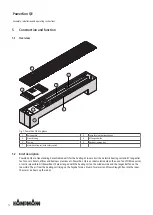
Page 12: ...iption PowerKon QE are free standing decentralised units for the heating of room air with an electric heating coil and EC tangential fan for use in hotels offices and business premises etc PowerKon QE...

Page 13: ...ly suspended standing Ensure that the airflow can circulate freely Provide adequate space for appropriately sized flow and return water connections on site Connection to the pipe net work There is a p...

Page 14: ...ating instructions 14 6 2 1 Installing the unit Dimensions Fig 2 Dimensions of the PowerKon QE 1 Window side 2 Room side A 825 mm 1250 mm 1700 mm B 400 mm 835 mm 1270 mm Fixing points Fig 3 All dimens...

Page 15: ...PowerKon QE Assembly installation and operating instructions 15...

Page 16: ...PowerKon QE Assembly installation and operating instructions 16...

Page 17: ...PowerKon QE Assembly installation and operating instructions 17...

Page 18: ...PowerKon QE Assembly installation and operating instructions 18...

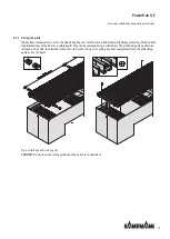
Page 19: ...tory fitted on both longitudinal sides of the duct as a safety guard They can be removed using a screwdriver The grille fixing only needs to be removed on one side the electrical connection side when...

Page 20: ...cy Hz Nominal power W Nominal current A Ri analogue input k Protection class IP Protection class 825 230 50 800 3 5 100 21 I 1250 230 50 1600 7 0 100 21 I 1700 230 50 2400 10 6 100 21 I Tab 3 Maximum...

Page 21: ...10 V AI1 Control signal 0 10 V Heat output 0 100 Ri 100 K NTC 10K AI2 temperature sensor X3 Safety temper ature limiter Safety temperature limiter RPM Input signal of the number of revolutions of the...

Page 22: ...2 sec Off 0 8 sec On 0 2 sec Off 0 8 sec On 0 2 sec Off 2 sec 5 x flashing On 0 2 sec Off 0 8 sec On 0 2 sec Off 0 8 sec On 0 2 sec Off 0 8 sec On 0 2 sec Off 0 8 sec On 0 2 sec Off 2 sec Alternating...

Page 23: ...luation Control signal 0 10V DC Note 2V bis 9 5V speed 0 to 100 1 2 4 W2 N PE L 1 2 gn ge 3 W1 Main supply 230V 50 Hz Fuse protection on site Observe the technical data table Control 0 10V DC via BMS...

Page 24: ...GND DI 1 2 Optional Ext evaluation Fault signal Max 60V 1A 2 1 1 1 2 3 1 2 3 24V GND 0 10V Junction box PowerKon QE Unit No 2 AI1 GND L N PE 1 2 gn ge NC NO C 1 2 1 2 Main supply 230 VAC speed Option...

Page 25: ...whether all components are properly fitted Check whether all dirt such as packaging or site dirt has been removed Electrical tests Check whether all lines have been properly laid Check whether all li...

Page 26: ...e controller type 146928 room temperature controller for 2 and 4 pipe applications surface moun ted wall installation on a flush mounted box setpoint display by threshold arrows heating or cooling via...

Page 27: ...he proper and trouble free operation of the equipment If there are signs of increased wear during regular checks shorten the required maintenance intervals to the actual wear and teat Contact the manu...

Page 28: ...ch off the unit and prevent it from being reconnected if rectifying the fault requires work in the hazard area Immedi ately advise a supervisor on site about the fault 4 Either rectify the fault yours...

Page 29: ...Articles No PowerKon QE 137 Type Mod le N d article Typ Model Nr artyku u Typ Model slo v robku auf das sich diese Erkl rung bezieht mit der den folgenden Norm en oder normativen Dokumenten bereinstim...

Page 30: ...14 30 EU EMV Richtlinie 2014 35 EU Niederspannungsrichtlinie Frank Bolkenius Lingen Ems den 07 07 2022 ___________________________________ Ort und Datum der Ausstellung Name und Unterschrift des Befug...

Page 31: ...PowerKon QE Assembly installation and operating instructions 31...

Page 32: ...PowerKon QE Assembly installation and operating instructions 32 Table Tab 1 Limits of operation 6 Tab 2 Operating voltage 6 Tab 3 Maximum electrical rating values electromechanical model 230 V 20...

Page 33: ......

Page 34: ......

Page 35: ......

Page 36: ...oducts peri meter heating powerkon qe Country Contact Great Britain Kampmann UK Ltd Dial House Govett Avenue Shepperton Middlesex TW17 8AG T 44 1932 228592 F 44 1932 228949 E info kampmann co uk W Kam...

Reviews: