Typ 148916 –
I487/01/14/1 GB . SAP-Nr. 1181279
5 21 831 00
Safety information
Expert electricians only may open this device in due compliance with the wiring diagram
shown in the housing cover / on the housing / represented in the corresponding operating
instructions. All expert electricians charged with the execution of such works must comply
with the relevant safety regulations currently operative and in force.
Caution:
The operation
of the controller in the vicinity of other devices that do not comply with the EMC directives
may affect its functions. The company charged with the installation of the device must,
after the completion of the installation works, instruct the user of the control system into
its functions and in how to operate it correctly. These operating instructions must be kept at
a place that can be accessed freely by the operating and/or servicing personnel in charge.
Table of contents
1.
Application
2.
Functional description
2.1 Application in 2-pipe systems with either manual or automatic
heating/cooling changeover
2.2 Application in 4-pipe systems
2.3 Option to select between internal or external sensor-based operation
2.4 Fan function
2.5 ON/OFF function
2.6 Antifreezing function
2.7 Contact inputs ON/OFF – ECO
2.8 Emergency operation function in the event of a sensor breakage or sensor short-circuit
3.
Installation / mounting
3.1 Limitation of the temperature setting range
4.
Accessories
5.
Technical data
6.
Data table with external sensor data (characteristic curve)
7.
Dimensioned drawings and connection diagrams / overview of DIP switch positions
8.
Warranty
1. Application
This room temperature controller has been specially devised for the triggering of fan coils,
fan coil devices and other temperature control systems used for the control of normally
closed valve-equipped 2- or 4-pipe systems. With these systems, the controller is either
used as single room temperature controller (internal sensor) or as external controller that
operates based on the data delivered to it by a remote sensor. Regarding other applications
not to be foreseen by the manufacturer of this device, the safety standards concerning
these applications need to be followed and adhered to. Regarding the aptitude of the device
for any such other application, please refer to section 8. herein (Warranty).
2. Functional description
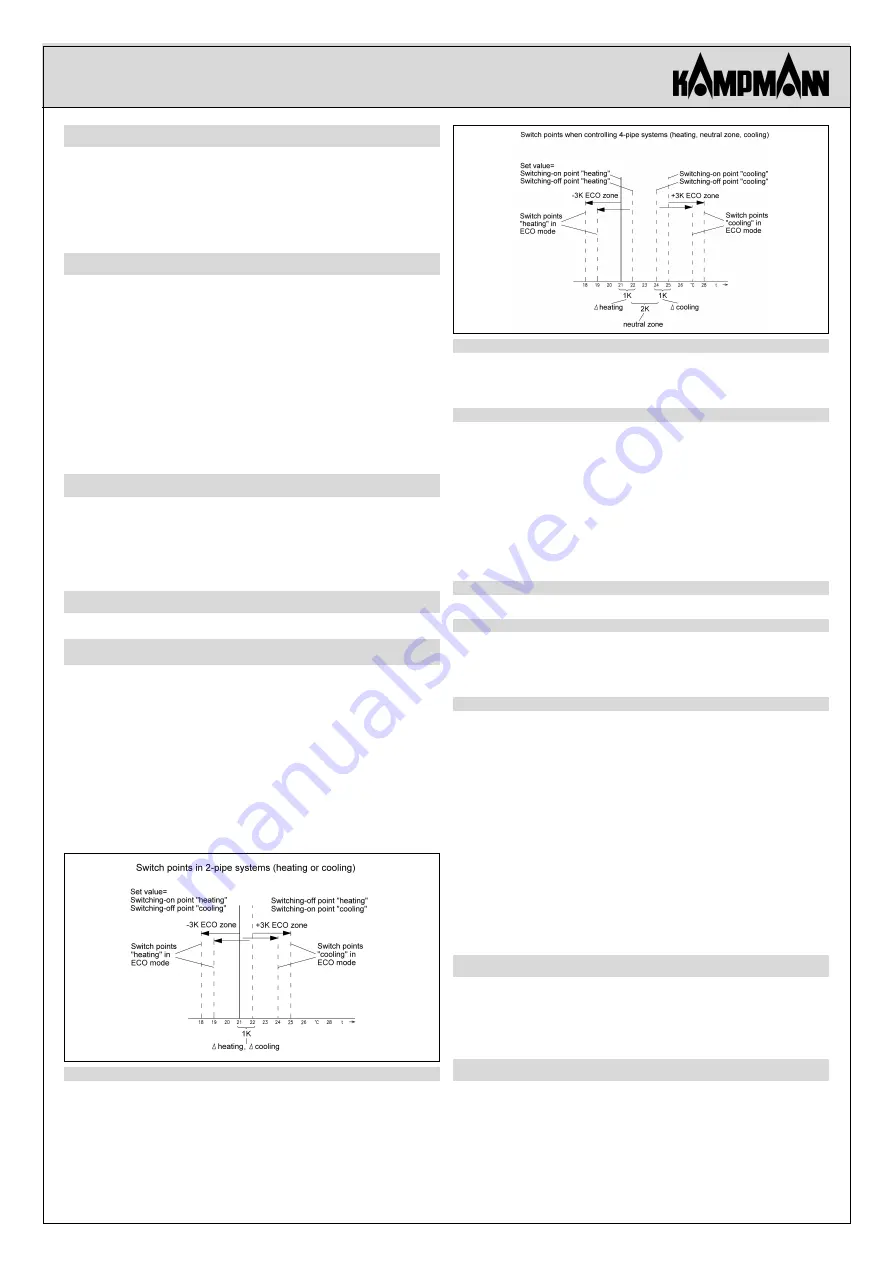
The switching difference of the controller comes to 0.5 K. The control characteristics of the
following control system examples assume the occurrence of a control deviation of 1K.
2.1 Application in 2-pipe systems with either manual or automatic
heating/cooling changeover
The switch S3 (see section 7.) enables to adjust the controller to the existing pipe system.
If using it for the control of 2-pipe systems (factory setting), the output at terminal 2 trig-
gers the heating/cooling valve. The heating/cooling changeover contact (terminals 14 and
15) determines the direction of operation controlled by the device. Contact closed =
heating, contact open = cooling. Optionally, a flow sensor (see sections 4. and 6.) can be
connected in place of the contact, which allows to achieve the automated changeover
between heating and cooling mode. Regarding the changeover points when using a flow
sensor, please refer to section 5.
Control characteristic during operation in heating mode
The heating is being activated each time the temperature falls below the adjusted set value.
As soon as the temperature rises by a value that corresponds to the switching difference of
approx. 1K, the heating is being deactivated again. The desired temperature value will not
be underrun, therefore, which guarantees optimum comfort.
Cooling mode control characteristics
Once the adjusted temperature value is not attained, operation in cooling mode is being de-
activated. After a rise of the temperature approx. 1K (switching difference), operation in
cooling mode is being activated again.
2.2 Application in 4-pipe systems
The switch S3 (see section 7.) enables to adjust the controller to the existing pipe system.
If using the device for the control of 4-pipe systems, the heating output at terminal 1
triggers the heating operations and the cooling output at terminal 2 the cooling operations.
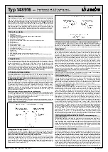
Control characteristics when operating with neutral zone
The neutral zone can be set within a range from 0.5 K to 6 K (factory setting 2 K) and begins
at the heating switch-off point. If set to 21°C, the heating will be set to a temperature above
21°C while operating in heating mode and down to a temperature below 25°C while opera-
ting in cooling mode. In both heating and cooling mode, the switching difference comes to
approx. 1K. If set to 21°C, the heating switch-off point is thus at approx. 22°C and the
cooling switch-off point at approx. 24°C.
2.3 Option to select between internal or external sensor-based operation
The selector switch S4 (see section 7.) allows to set the device for either the utilisation of
the internal (factory setting) or the external sensor. The terminals 12 and 13 have been
provided for the connection of the external sensor. For a selection of suitable sensors,
please refer to sections 4., “Accessories”, and 6., “Data table with external sensor data
(characteristic curve)”.
2.4 Fan function
The controller described here is equipped with a 3-step switch for the selection of the desi-
red fan stage. The switch S2 (see section 7.) allows to set the fan ON (factory setting) or
OFF within the neutral zone. In order to enable the internal sensor to detect the room tem-
perature in an optimal manner, we recommend setting the fan in the neutral zone to ON
when controlling temperature equalization systems that feature a fan-assisted convection of
the ambient air. The fan is permanently activated in this case. If setting the fan to OFF
within the neutral zone, it remains deactivated across the entire temperature range, i.e. bet-
ween the switch-off points “heating” and “cooling” (= neutral zone, see diagram “Switch-
points within 4-pipe systems”), the activation of the fan while operating in heating mode
takes place above the corresponding switch-point level and, while operating in cooling
mode, is deactivated below the related switch point level. Each time after deactivation of the
heating or cooling mode, the fan performs a 5-minute overrun. To allow the triggering of
fan motors with separated windings or fan motors using a step-down transformer, the trig-
gering of the fan has been realised in a potential–free manner.
Caution:
No protection class
III fans or other protection class III consumers must be connected.
2.5 ON/OFF function
Actuating the ON/OFF switch activates or deactivates the control system. The antifreezing
function remains active even after the deactivation of the system.
2.6 Antifreezing function
The antifreezing function protects the controlled room against cooling down thoroughly
and thus against any frost damage due to it. In the event the temperature measured by the
activated internal or external sensor falls below approx. 5°C, the valve output “heating”
within the controlled 4-pipe system is activated. In 2-pipe systems, the same applies with
regard to the valve output “heating/cooling”, which is activated along with the fan output.
The controller is deactivated again, once a temperature of 6°C is being exceeded.
2.7 Contact inputs ON/OFF – ECO
The following function can be triggerd via the terminals 16 and 17 (safety extra low voltage)
depending on the position of the switch S1: (see section 7.) Switch S1 in the position “ON”
(factory setting)
씮
ECO function (energy economizing function). The triggering of the energy
economizing function is effected by an external contact (terminals 16 and 17). Once this
function is activated, the temperature is, while operating in heating mode, being set to a tem-
perature that, in relation to the set value, is by 3 K lower and, while operating in cooling mode,
to a temperature that transcends the set value by 3 K (ECO zone ±3 K). When controlling 4-
pipe systems, the neutral zone of 2 K is being extended by ±3 K once the ECO function has
been triggered. If, for instance, the ECO function is triggered after adjusting a set value of
21°C and the seting of a neutral zone of 2 K, the control operations performed by the system
in heating mode aim at reaching a temperature of 18°C and aim at reaching a temperature of
28°C while operating in cooling ode (see sections 2.1 and 2.2). This enables to save energy in
a room- and/or floor-wise manner. The ECO function is mainly used in hotels where, apart
from the saving of energy, the standby function is necessary in order to hand over the room
to the hotel guest in a neither too warm nor too cold condition and where the well-being
temperature shall be attained in this room as soon as possible after it has been occupied by a
guest. It is impossible to bring the system to perform control operations aimed at reaching
temperatures below a level of 5°C by setting the temperature to a minimum value and trigge-
ring the ECO function. Contact closed = normal operation, contact open = operation in ECO
mode. Switch S1 set to “OFF”
씮
The antifreezing function is active. An external contact
(window contact or timer, f. ex.) connected to the terminals 16 and 17 enables to deactivate
the control operations performed by the system from a distance. Contact closed = control
system activated, contact open = control system deactivated.
2.8 Emergency operation function in the event of a sensor breakage or
sensor short-circuit
The emergency operation shall avoid the occurrence of critical temperature conditions in
the room to be controlled if a sensor breakdown or short-circuit occurs. Once this is the
case, the heating valve output is being triggered at a level that is equivalent to 30% of the
normal operating time (3 minutes ON, 7 minutes OFF). To prevent the related room from
cooling down thoroughly and ensure its protection against frost damages, heating in 2-pipe
systems thus takes place if the heating/cooling contact is in heating position and takes
place in 4-pipe systems at the above-mentioned efficiency 30% level.
3. Installation / mounting
The device is, depending on the type or the packaging size, either delivered in closed, or, in
order to facilitate its installation, in opened condition. After its installation on the wall or on an
UP box with the aid of the adapter plate JZ-17, its electrical connection and the
safe separa-
tion between mains voltage and safety extra low voltage using the enclosed partition (see
section 7.)
, the housing cover needs to be closed by hooking the lower hooks in the housing
and folding the cover upward until it clicks into place. Following this, the housing cover should
be secured using the accompanying screw. For the opening of the device follow the above
steps in inverse order. Caution: The device must not be mounted on electrically conductive
surfaces. When using an external sensor, care must be taken to ensure that the sensor line is
not laid in parallel to line voltage carrying cables or lines. Where parallel laying cannot be avoi-
ded, a shielded line is to be used and the shielding to be connected to the terminal 13, 15 or
17. In order to ensure the easy replacement of a defective sensor, the sensor including its line
needs to be laid inside an empty conduit in a replaceable manner.
Room thermostat with “ECO” switching input
or frost protection monitoring after “device OFF”


