Insufficient coolant can damage the engine.
Insufficient coolant will cause the engine to overheat. Overheating can cause serious dam‐
age to the engine.
➤ Check the coolant level daily.
➤ Top up the coolant as necessary.
Checking coolant level
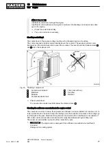
The coolant level in the engine cooling circuit must be checked daily prior to startup.
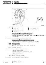
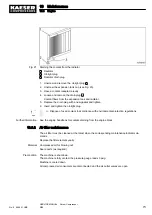
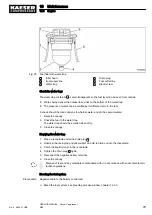
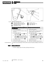
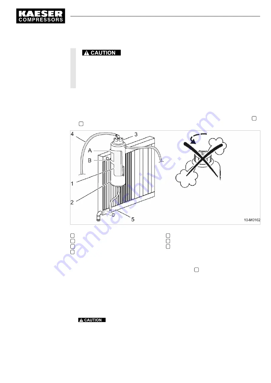
The coolant expansion tank is located directly above the radiator. The expansion tank is semi-
transparent so the coolant level can be seen from outside. The level should be between marks
A
and
B
when the engine is cold.
Fig. 20 Checking coolant level
1
Coolant level indicator
A
Maximum
B
Minimum
2
Coolant expansion tank
3
Filler neck with cap
4
Overflow
5
Radiator
➤ Check coolant level.
Top up when the coolant level falls below the minimum level
B
.
Checking the antifreeze concentration in the engine coolant
The coolant is a mixture of clean, fresh water and antifreeze/corrosion inhibitor. For reasons of cor‐
rosion protection and the need to raise the boiling point, the coolant must remain in the cooling sys‐
tem throughout the year. Maximum frost protection is ensured with an antifreeze concentration of
55% volume as frost protection and heat transfer properties deteriorate beyond this point.
The maximum permissible service life of the coolant is 2 years.
1.
The engine can be damaged if the antifreeze concentration is insufficient.
Corrosion
Damage to the cooling system
10 Maintenance
10.3 Engine
No.: 9_9446 01 USE
SERVICE MANUAL Screw Compressor
M26
71
Summary of Contents for M26
Page 1: ...SERVICE MANUAL Screw Compressor M26 No 9_9446 01 USE...
Page 191: ...13 Annex 13 3 Dimensional drawing No 9_9446 01 USE SERVICE MANUAL Screw Compressor M26 183...
Page 193: ...13 Annex 13 3 Dimensional drawing No 9_9446 01 USE SERVICE MANUAL Screw Compressor M26 185...
Page 194: ...13 Annex 13 4 Electrical Diagram No 9_9446 01 USE SERVICE MANUAL Screw Compressor M26 187...
Page 195: ...13 Annex 13 4 Electrical Diagram 188 SERVICE MANUAL Screw Compressor M26 No 9_9446 01 USE...
Page 196: ...13 Annex 13 4 Electrical Diagram No 9_9446 01 USE SERVICE MANUAL Screw Compressor M26 189...
Page 197: ...13 Annex 13 4 Electrical Diagram 190 SERVICE MANUAL Screw Compressor M26 No 9_9446 01 USE...
Page 198: ...13 Annex 13 4 Electrical Diagram No 9_9446 01 USE SERVICE MANUAL Screw Compressor M26 191...
Page 199: ...13 Annex 13 4 Electrical Diagram 192 SERVICE MANUAL Screw Compressor M26 No 9_9446 01 USE...
Page 200: ...13 Annex 13 4 Electrical Diagram No 9_9446 01 USE SERVICE MANUAL Screw Compressor M26 193...
Page 201: ...13 Annex 13 4 Electrical Diagram 194 SERVICE MANUAL Screw Compressor M26 No 9_9446 01 USE...

