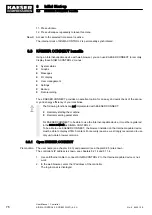
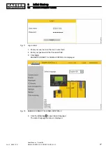
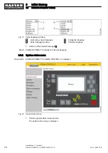
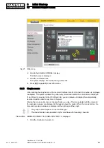
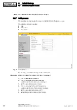
8.4 Commissioning the KAESER i.Box
The KAESER i.Box is commissioned at the customer site by the authorised service partner.
The SIM card can be activated only at the final installation site because it is linked to the na‐
tional wireless network at that location.
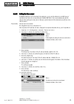
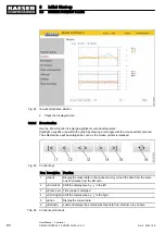
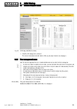
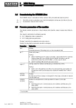
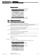
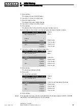
8.5 Pressure parameters of the machine
This chapter contains instructions on how to display and adjust the pressure parameters of the ma‐
chine.
The chapter is divided into the following sections:
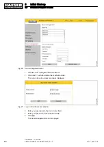
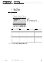
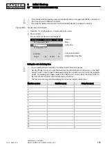
■ 8.5.1: Displaying pressure parameters
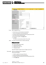
■ 8.5.2: Setting pressure parameters
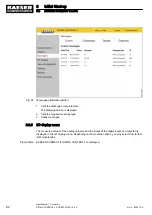
"Display" means that the parameter will only be shown.
"Setting:" means that the parameter can also be changed.
Parameters
Explanation
pRV
Display:
Actuating pressure of the safety valve on the oil separator tank
pE
12)
Pressure increase
Setting:
■ pE SP: Switching point for pressure increase; upper safety limit for maximum
machine pressure; in an external LOAD controller, this value is used to
switch the machine from LOAD to IDLE
12)
in the event of a fault.
■ pE SD: Switching differential of pressure increase
ΔpFC
12)
Limiting value for machines with frequency-controlled drive (SFC).
Setting:
■ ΔpFC: Limit of lowest flow rate. When the value [switching point system tar‐
get pr
ΔpFC] is exceeded, the compressor switches from LOAD to
IDLE.
Nominal
pressure
Display:
Nominal press.:The compressor is designed for this pressure (maximum network
nominal pressure)
Setpoint
pressure
Network nominal pressure can be regulated to 2 values: pA and pB.
Setting:
■ Switching point
pA or control pressure pA in machines with frequency con‐
verter (SFC)
■ Switching point
pB or control pressure pB in machines with frequency con‐
verter (SFC)
12)
not for SXC
8
Initial Start-up
8.4
Commissioning the KAESER i.Box
No.: 9_9450 12 E
User Manual Controller
SIGMA CONTROL 2 SCREW FLUID ≥5.0.X
89