Installation
Installation Manual
22
k2evo702 - 201610
Kaba c-lever and variants
4.3
Installing the coupling unit
NOTICE
Danger of damage to electronic components from electrostatic discharge.
If electronic printed circuit boards and components are handled incorrectly, damage
may occur which leads to their complete breakdown or sporadic faults.
•
When installing and repairing the product, the general ESD protective measures
are to be observed.
4.3.1
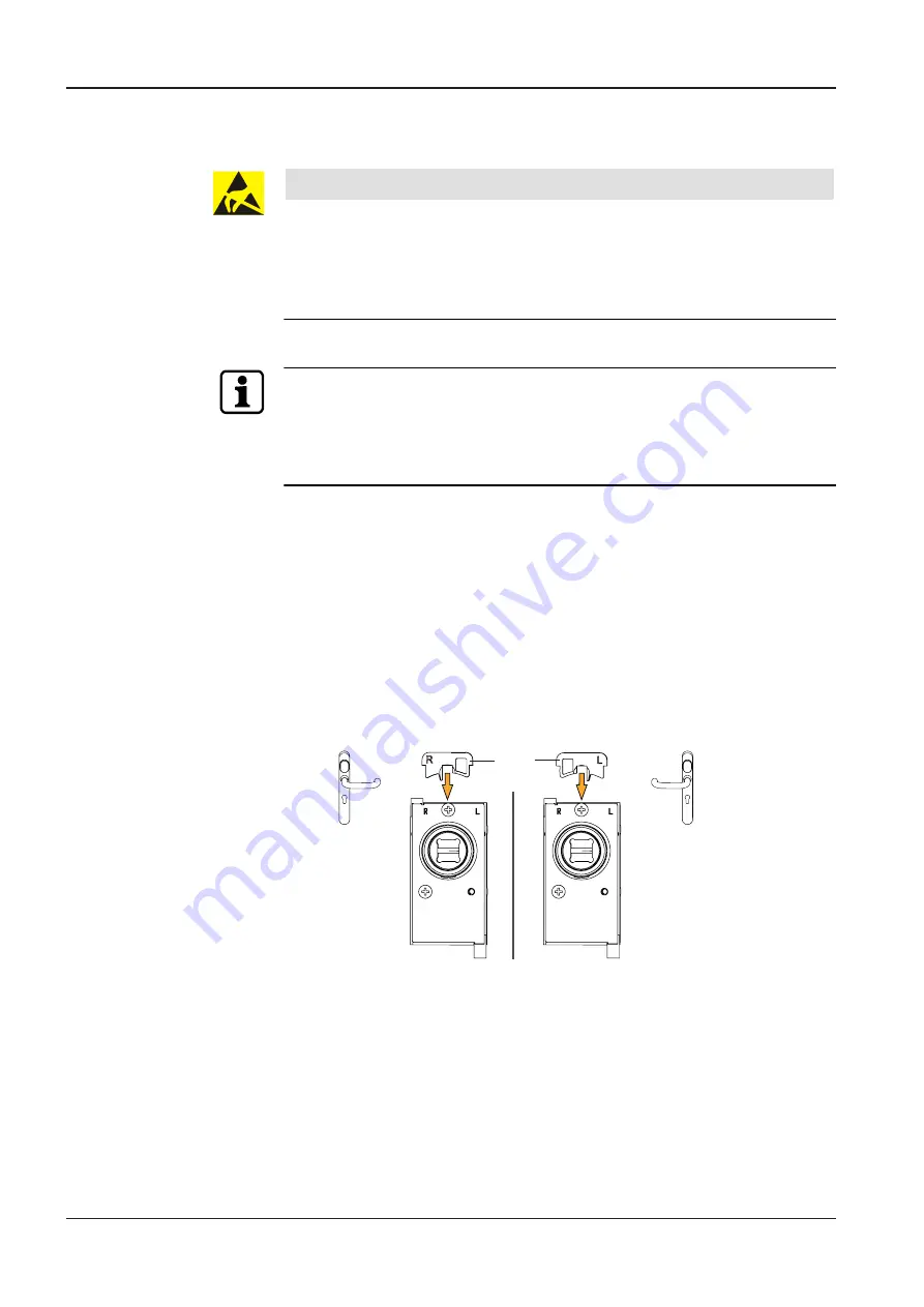
Inserting the direction pin
The orientation of the outside lever handle determines the position of the direction
pin. The direction pin has a marking on both sides (R or L); the same markings are
located on one side of the front of the coupling unit housing. The direction pin is in-
serted into the coupling unit in such a way that when an outside lever handle is
turned right or left the "R" or "L", respectively, matches the marking on the coupling
module.
Requirement:
•
Lever handle exists for spindle (9 mm) of coupling unit
Procedure:
1.
Align the direction pin (10); see information above.
2.
Place the lever handle with the outside shield on the spindle
of the coupling unit.
3.
Note: turn the spindle as far as it will go in order to make
it easier to insert the direction pin.
Turn the lever handle to the left as far as it will go for a right
side and to the right for a left side.
10
4.
Insert the direction pin.
-> Audibly clicks into place.
5.
Release the lever handle.
Result:
The direction pin is installed in the coupling unit for the desired
door side.


