background image

Service

Operating Manual

38

k1evo821 - 201606

Kaba mechatronic cylinder surface

Round profile

8.2

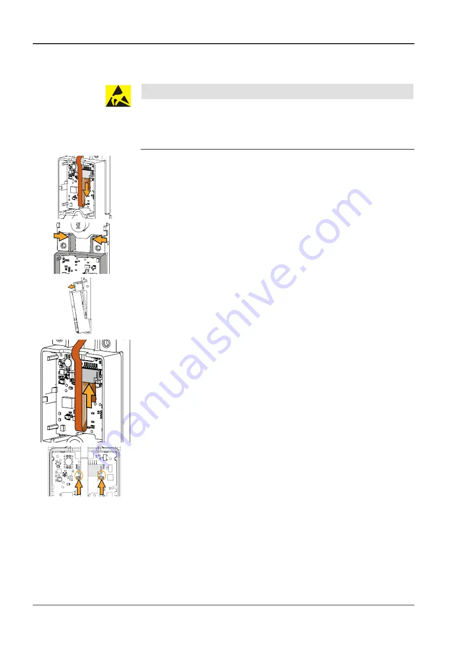
Replacing the e-module

NOTICE

Danger for electronic components due to electrostatic discharge.

Improper handling can damage or destroy electrostatically sensitive components on
printed circuit boards (PCB).

General ESD protective measures must be observed and applied.

ü

Rotary knob, housing and battery removed

1. Open the sleeve lock.

2. Remove the flat ribbon cable.

3. Push both catches together as shown.

4. Lift the e-module out of the retaining plate.

5. Insert the new e-module at the bottom of the retaining plate.

6. Push the upper catches into the retaining plate.

ð

The catches lock in place.

7. Insert the flat ribbon cable into the sleeve so that the strip conductors on the flat

ribbon cable are visible.

8. Close the lock.

9. Secure Fitting the retaining plate, housing and cover

 [

}

 4.1.8]

.

10.

Secure [

}

 4.1.9]

 the rotary knob.

Summary of Contents for 1547-K5

Page 1: ...Kaba mechatronic cylinder surface Operating Manual EN k1evo821 201606 Round profile ...

Page 2: ...ne 41 44 931 61 11 www kaba com Kaba GmbH Access Workforce Management Albertistraße 3 78056 Villingen Schwenningen Germany Phone 49 7720 603 0 www kaba com This document must not be reproduced in any way or otherwise further used without the written consent of Kaba AG All product names are trademarks of the respective companies Copyright 2016 Kaba AG All rights reserved k1evo821 201606 Round profi...

Page 3: ...nsions 12 3 5 Conformity 13 4 Installation 14 4 1 Installing the mechatronic cylinder and surface mounted e module 14 4 1 1 Tools required 14 4 1 2 Installation versions 14 4 1 3 Installation without body cut out 14 4 1 4 Dismantling the rotary knob 14 4 1 5 Dismantling the housing 14 4 1 6 Undoing and removing the retaining plate 15 4 1 7 Fitting the cylinder in the mortise lock 16 4 1 8 Fitting ...

Page 4: ...media 29 5 8 Deleting individual B masters 30 5 9 Deleting all user media and B masters 31 5 10 INI reset with master media for whitelist and CardLink 32 5 11 Programming with the programmer 1460 33 6 Operation 34 6 1 Operating the mechatronic cylinder 34 6 2 Opening with a user key 34 7 Maintenance 35 7 1 Maintenance table 35 7 2 Cleaning 35 7 3 Function check 36 8 Service 37 8 1 Replacing the ba...

Page 5: ...vities and to minimise these risks for themselves and others It is the responsibility of the service personnel to ensure that the condi tions stated by the manufacturer and the applicable regulations and standards are complied with when carrying out these activities 1 3 Contents and purpose The contents of these instructions are limited to the installation operation mainten ance and servicing of t...

Page 6: ... dangerous situation that could lead to serious injury or death CAUTION Low risk Denotes a potentially dangerous situation that could lead to minor injury NOTICE Important information on the correct use of the product Failure to comply with these instructions could lead to malfunctions The product and or objects in the local vicinity could be damaged 1 7 Notes Notes marked with this symbol must be...

Page 7: ...he instructions 2 3 Use in emergency exit or panic door locks WARNING Risk of personal injury or death Improper use or incorrectly installed mechatronic cylinders can lead to emer gency exit locks or panic door locks and doors not opening The use of a mechatronic cylinder must be checked carefully before using it in locks with a panic function ð The compact mechatronic cylinder and the mechatronic...

Page 8: ...ges of printed circuit boards Do not touch printed circuit boards or connecting plugs Put removed components on an anti static surface or in an anti static shielding container Avoid contact between printed circuit boards and clothing The wrist strap only protects the printed circuit boards from static electricity on the body Damage can still occur due to static electricity on clothing Only transpo...

Page 9: ...surface mounted housing with the e module is fixed to the inside of the door directly on the cylinder The lock can only be actuated if the user key Kaba smart key is authorised electron ically Access authorization and operation condition are signalled acoustically When used outdoors the cylinder must be protected against sustained rainfall using a weather guard 3 1 1 Structure 3 1 1 1 Thumbturn cy...

Page 10: ... Mechatronic cylinder 3 Wireless module optional 8 Locking module 4 Flat ribbon cable 9 Antenna 5 E module 1 6 Surface mounted e module 3 2 Scope of delivery 1 mechatronic cylinder 1 surface mounted e module 1 forend screw pozi type 1 battery CR2 lithium type 1 quick guide 3 3 Accessories optional Relevant system software and programming tools Wireless module optional Adapter plates ...

Page 11: ...ersions 30 mm Door opens outwards standard rotary knob door rebate 10 mm Power supply Battery 3 V CR2 Lithium type Operating environments Protection type IP41 Temperature 25 C 70 C The temperature range depends on the battery manufacturers specifica tions Humidity 0 95 rH non con densing Climate Not suitable for heavily corrosive atmospheres chlorine ammonia Standards Durability 100 000 cycles Cyc...

Page 12: ...atronic cylinder surface Round profile 3 4 1 Dimensions Double cylinder version LA M5 16 19 5 25 Ø 22 11 24 8 LB B 16 B 13 7 79 20 4 2 3 5 4 mm 127 37 6 Thumbturn knob version 32 47 5 2 5 3 6 3 11 LA LB B 16 M5 16 B 19 5 24 25 Ø 22 8 13 7 79 20 4 2 3 5 4 mm 127 37 6 ...

Page 13: ...or vertical rosette hole 3 5 Conformity This product conforms to the following standards EN 60 950 1 2014 08 EN 301 489 1 V1 9 2 2011 EN 301 489 3 V1 6 1 2013 EN 300 330 1 V1 8 1 2014 EN 300 330 2 V1 6 1 2014 Wireless module optional EN 300 328 V1 9 1 2015 04 as set out in provisions of EU Directives R TTE 2014 53 EC RoHS This device is in compliance with the provisions of Directive 2011 65 EC of ...

Page 14: ...ut out and the retaining plate must be un screwed Installing the internal fitting with body cut out 4 2 The internal fitting with body cut out and the retaining plate must be un screwed 4 1 3 Installation without body cut out 4 1 4 Dismantling the rotary knob The rotary knob must be dismantled for installation with a rotary knob cylinder ü Tool multitool available 1 Insert the multitool with the n...

Page 15: ...do the screws as far as necessary for the housing to be removed ð Both screws remain in the housing 5 Remove the housing 6 Open the sleeve lock 7 Remove the flat ribbon cable 4 1 6 Undoing and removing the retaining plate 4 mm 1 Loosen the screw from the retaining plate NOTICE Avoid damaging the flat ribbon cable Remove the flat ribbon cable so that it cannot be pinched shorn or damaged due to imp...

Page 16: ...ter plate depending on the installation situation ü Internal fitting unscrewed from the door depending on the installation situation 1 Align the cylinder cam parallel to the cylinder pin 2 Slide the cylinder with the surface mounted e module onto the mortise lock from the inside of the door 3 Align the cylinder antenna in the mortise lock Note The antenna 3 must be at least 7 5 mm from the externa...

Page 17: ...or damaged by improper handling 1 Guide the flat ribbon cable through the fitting and or adapter plate 2 Tighten the fitting 3 Guide the flat ribbon cable through the retaining plate as shown 4 Insert the retaining plate on the cylinder 4 mm 4 Nm 16 5 Push the retaining plate firmly against the door leaf 6 Tighten the screw using a maximum of 4 Nm 7 Insert the flat ribbon cable into the sleeve so ...

Page 18: ...upwards using your finger 15 Push the cover against the housing The cover locks in place 16 Remove the protective film from the cover 17 Check 7 3 that it works 4 1 9 Inserting the rotary knob 1 Align the rotary knob with the notch as shown 2 Insert the rotary knob on the cylinder axis ð The rotary knob locks in place 3 Check the rotary knob is sitting securely by pulling on it 4 1 10 Tightening t...

Page 19: ...with the narrow pawl between the Knob and the fitting 2 Press the multitool against the fitting ð The locking spring will release 3 Remove the Thumbturn knob 4 2 2 Dismantling the housing 1 Push both catches upwards using the multitool ð The catches will be released 2 Remove the cover by pulling the bottom section forwards 3 Remove the battery 4 Undo both screws Note Only undo the screws as far as...

Page 20: ...nder in the mortise lock 7 5 1 2 3 16 1 Door 2 External fitting or external rosette 3 Antenna ü Fitted mortise lock ü Fitted adapter plate depending on the installation situation ü Internal fitting unscrewed from the door depending on the installation situation 1 Align the cylinder cam parallel to the cylinder pin 2 Slide the cylinder with the surface mounted e module onto the mortise lock from th...

Page 21: ...or damaged by improper handling 1 Guide the flat ribbon cable through the fitting and or adapter plate 2 Tighten the fitting 3 Guide the flat ribbon cable through the retaining plate as shown 4 Insert the retaining plate on the cylinder 4 mm 4 Nm 16 5 Push the retaining plate firmly against the door leaf 6 Tighten the screw using a maximum of 4 Nm 7 Insert the flat ribbon cable into the sleeve so ...

Page 22: ...film The battery is inserted 13 Guide in the top of the cover 14 Push both catches upwards using your finger 15 Push the cover against the housing The cover locks in place 16 Remove the protective film from the cover 17 Check 7 3 that it works 4 2 6 Inserting the rotary knob 1 Align the rotary knob with the notch as shown 2 Insert the rotary knob on the cylinder axis ð The rotary knob locks in pla...

Page 23: ...n header parallel to the e module so that the pin header and wireless module are not damaged NOTICE Danger for electronic components due to electrostatic discharge Improper handling can damage or destroy electrostatically sensitive components on printed circuit boards PCB General ESD protective measures must be observed and applied ü Battery removed ü Assembled flat ribbon cable 1 Insert the wirel...

Page 24: ...e PCB 4 4 Additionally securing for the retaining plate A B Depending on the installation situation the retaining plate can also be secured using screws to an adapter plate that was previously screwed to the door leaf For the dimensions of the adapter plates see 3 4 1 Dimensions Requirements for screws at position A 2 x M4 screws not included in the scope of delivery Screw head diameter 8 mm Requi...

Page 25: ...ia A B master or B master or the programmer 1460 and the system soft ware To program and operate mechatronic cylinders always briefly insert the program ming media and user keys into the cylinders 5 1 Initial programming of MRD components When first used multi RFID MRD components are set to the technology in which the components are used with a master LEGIC or MIFARE The components then be have as...

Page 26: ...fly approx 5 mm The cylinder is activated 3 Hold the card holder with the medium in front of the cylinder as shown The acoustic signal will sound as long as the medium is within the an tenna field of the cylinder 5 4 User media All User key are organised under a B master User key NOTICE Lost User key should be immediately blocked and deleted from all components Delete lost User key in the KEM syst...

Page 27: ...Operating Manual Programming 27 k1evo821 201606 Kaba mechatronic cylinder surface Round profile 5 5 A B and B structures A B structure B structure Master A Master B User media ...

Page 28: ...eep 1 Master B 1 s Launch programming mode B master approx 1 s insert into the cylinder 1 x short Beep 2 User 1 1 s Program User key User key approx 1 s insert into the cylinder 1 x short Beep 3 User 2 3 1 s Additional User key approx 1 s insert into the cylinder 1 x short Beeeep 4 Master B 1 s To complete B master approx 1 s insert into the cylinder Note If no master medium is held up within 20 s...

Page 29: ...B master approx 1 s insert into the cylinder 1 x short 2 User 3 s Beep Beep Delete User key User key approx 3 s insert into the cylinder 2 x short Beeeep 3 Master B 1 s To complete B master approx 1 s insert into the cylinder Note If no master medium is held up within 20 seconds pro gramming mode ends automat ically and one long acoustic sig nal sounds 1 x long Table 2 Deleting individual user med...

Page 30: ...er A 1 s Launch programming mode A master approx 1 s insert into the cylinder 1 x short 2 Master B 10 s Beep Beep Delete B master and all user me dia B master approx 10 s insert into the cylinder 2 x short Beeeep 1 Master A 1 s To complete A master approx 1 s insert into the cylinder Note If no master medium is held up within 20 seconds pro gramming mode ends automat ically and one long acoustic s...

Page 31: ...on 1 Master B 10 s Beep Beep insert into the cylinder B master approx 10 s All User key under the B mas ter are deleted 2 x short 1 x long1 2 1 x short Table 4 Delete all user media B master deletion Action Beep Beep 1 Master A 10 s insert into the cylinder A master approx 10 s All B masters under the A mas ter will be deleted 2 x short 1 x long1 2 1 x short Table 5 Deleting all B masters Key 1 Fi...

Page 32: ... INI reset will be carried out after 15 s after 10 s 1 x long 1 x short after 15 s 2 x short Beep Beep 1 Master A 15 s A B master structure A master approx 15 s insert into the cylinder the INI reset will be carried out after 15 s after 10 s 1 x long 1 x short after 15 s 2 x short Table 6 INI reset with master media for whitelist INI reset for CardLink INI reset with master Action 1 Master B 15 s ...

Page 33: ...an be configured and programmed and the firmware FW can be updated using the programmer 1460 The V3 components can be configured and programmed using the programmer 1364 The firmware FW is updated together with the programmer 1460 A detailed description of programming can be found in the separate operating manual for the programmer 1460 and programmer 1364 ...

Page 34: ...e user key is the mechatronic key that has the required access authorisation and is authorised to open a door An acoustic signal denotes access authorisation Key 2 Round profile cylinders only have one permutation on the inside 6 2 Opening with a user key Before being used for the first time access authorisations for the relevant system software must be transmitted to the User key 1 2 Beep 1 Inser...

Page 35: ... cylinders Components Measures Interval All types of mechatronic cylin der Function check as specified in the in structions for the components 12 months Replacing the batteries 24 months Clock compon ents Checking and setting the time with the programmer 1460 12 months 7 2 Cleaning Only disinfection agents that are explicitly formulated for cleaning delicate metal surfaces and plastics may be used...

Page 36: ...installed and connected to cylinder ü Battery inserted in e module 1 Program 5 6 the cylinder manually 2 Insert 6 2 the authorised user key into the cylinder ð The acoustic signal denotes the access authorisation ð The lock can be actuated 3 Insert an unauthorised user key into the cylinder ð An acoustic signal sounds 4 x briefly ð The lock cannot be actuated ...

Page 37: ...ttom section forwards Whilst the battery is being changed all data access authorisations configurations and traceback is retained in the battery independent memory The clock settings are lost after 60 seconds 1 3 Remove the battery 1 4 Insert the new battery observing the polarity 1 x short acoustic signal 5 Guide in the top of the cover 6 Push both catches upwards using your finger 7 Push the cov...

Page 38: ... applied ü Rotary knob housing and battery removed 1 Open the sleeve lock 2 Remove the flat ribbon cable 3 Push both catches together as shown 4 Lift the e module out of the retaining plate 5 Insert the new e module at the bottom of the retaining plate 6 Push the upper catches into the retaining plate ð The catches lock in place 7 Insert the flat ribbon cable into the sleeve so that the strip cond...

Page 39: ...stem software via the wireless function are updated via the gateway e g clock time configurations The traceback can be read using the system software In standalone mode configurations can be transmitted using the programmer or can be changed with this e g adjusting the clock time A programmer can read the traceback and transmit it to the system software for eval uation Further steps are described ...

Page 40: ...ey to the programmer 1460 via the programming cable 2 Insert the valid master key into the cylinder briefly 3 Insert the adapter key into the cylinder 4 Open the Settings menu for the programmer 1460 5 Select Actuator 6 Select INI reset 7 Select Yes ð An acoustic signal sounds 2 x briefly to indicate that the INI reset was successful A detailed description of the INI reset can be found in the sepa...

Page 41: ... 9 V battery ready ü Authorised user key ready NOTICE Prevent damage to the emergency power supply The emergency power supply must not be turned in the cylinder as turning may damage it 1 1 Insert the emergency power supply into the cylinder 2 3 2 Press and hold the push button ð LED lights up red 3 Insert the authorised user key as shown clip towards door into the emergency power supply ð The loc...

Page 42: ...ry Empty Replace the batteries Door does not open authorisa tion via an authorised User key is confirmed by acoustic signals 8 x short Self test could not be completed Check or replace the locking unit Door does not open authorisa tion via an authorised User key is confirmed by acoustic signals 4 x short Key not programmed Outside the time window Program Key Check time profiles Door does not open ...

Reviews: