background image

2.2.1

KoreBot Connections

The KoreBot connection is pretty straightforward, the boards should be
simply stacked together. The KoreBot will provide the +3.3V power supply
to KoreSound.

2.3

Hardware Protection

2.3.1

Electrostatic Discharge Protection

As any electronic device, the KoreSound may be damaged by Electrostatic
Discharge.

K-Team S.A.

5

Summary of Contents for KoreSound

Page 1: ...Koresound user Manual Version 0 1 july 2004 ...

Page 2: ...ation SUN Microsystems Corp LabView National Instruments Corp MatLab MathWorks Corp Webots Cyberbotics Khepera K Team and LAMI Legal Notice The content of this manual is subject to change without notice All effort have been made to ensure the accuracy of the content of this manual However should any error be detected please inform K Team S A The above notwithstanding K Team can assume no responsib...

Page 3: ...reBot Connections 5 2 3 Hardware Protection 5 2 3 1 Electrostatic Discharge Protection 5 3 KoreSound Software 6 3 1 Overview 6 3 2 Linux Sound Driver 6 3 3 Basic Commands 7 3 4 Sound Programming on KoreBot 7 3 4 1 Sound devices 8 3 4 2 Sound device I O controls 9 3 4 3 Mixer device I O controls 10 K Team S A 2 ...

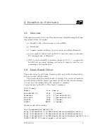
Page 4: ...The KoreSound board is a KoreBot extension that provides audio playback and recording capabilities It offers one audio stereo output and two audio stereo inputs This document presents how to use KoreSound K Team S A 3 ...

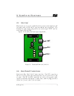
Page 5: ...IN2 Figure 2 1 describes the board main components IN1 OUT IN2 Figure 2 1 KoreSound hardware overview 2 2 KoreSound Connections KoreSound offers three Jack 3 5 mm connectors The OUT connector is used as an audio output and standard speaker can be used to hear sound or music The IN1 and IN2 connectors are used as two separate audio inputs and standard microphone or audio source must be plugged in t...

Page 6: ...orward the boards should be simply stacked together The KoreBot will provide the 3 3V power supply to KoreSound 2 3 Hardware Protection 2 3 1 Electrostatic Discharge Protection As any electronic device the KoreSound may be damaged by Electrostatic Discharge K Team S A 5 ...

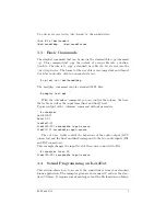
Page 7: ... is in the standard distri bution provided with KoreBot The sound driver is normally loaded at startup You can see all modules actually loaded with the lsmod command In the case the driver is missing you can force the loading using the modprobe command Typical output on KoreBot of the lsmod command bin lsmod Module Size Used by pxa uda1342 i2c 2504 0 unused soundcore 4072 2 pxa uda1342 i2c pxa aud...

Page 8: ...the volume the bass the treble as well as the input lines line1 and line2 level Typical output of the cutmixer command without paramters cutemixer vol 90 90 bass 0 0 treble 0 0 line1 50 50 recordable input source line2 0 0 recordable input source The vol bass treble control the behaviour of the audio output OUT connector and the line1 and line2 correspond to the two audio inputs IN1 and IN2 connec...

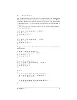
Page 9: ... be opened using standard C library open function fd open dev sound dsp O_RDWR if fd 0 opening failure fd open dev sound mixer O_RDWR if fd 0 opening failure To play sound or music the write function on device dev sound dsp must be used open a wave file to play wav_fd open test wav O_RD if wav_fd 0 opening error open the sound device dsp_fd open dev sound dsp O_RDWR if dsp_fd 0 opening error while...

Page 10: ...1 value close mix_fd while 1 record some samples from the sound device cnt read dsp_fd buf sizeof buf write the samples into the wave file write dsp_fd buf cnt As you could see in the last example the input channel is selected by calling the SOUND MIXER LINE1 I O control This I O control changes the gain level of the input 1 and selects the input 1 for recording 3 4 2 Sound device I O controls The...

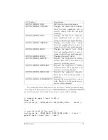
Page 11: ...s AFMT S16 LE The two example above shows how to use the ioctl function to change or to read sound settings change the sampling rate to 48 kHz val 48000 ioctl dsp_fd SNDCTL_DSP_SPEED val check if the channels are mono or stereo ioctl dsp_fd SNDCTL_DSP_CHANNELS val printf s n val 2 stereo mono 3 4 3 Mixer device I O controls The I O control are useful read and changes the settings of the mixer devi...

Page 12: ...C Reports the supported recording sources Each bit of the mask rep resents a recording source SOUND MIXER RECMASK Reports the supported recording channels Each bit of the mask rep resents a recording channel SOUND MIXER DEVMASK Reports the supported channels Each bit of the mask represents a channel SOUND MIXER STEREODEVS Reports the supported stereo chan nels Each bit of the mask reepre sents a s...

Page 13: ...K Team SA Ch de Vuasset CP 111 1028 Préverenges Switzerland ...

Reviews: