background image

8 of 40

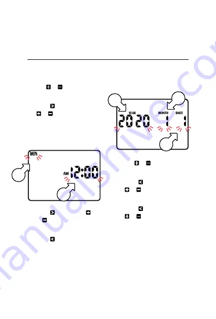
Set Current Time, Day and Date

1.  Turn the 

MAIN DIAL

 to


CLOCK-CALENDAR

2.  Use   or 


to adjust the 

flashing 

minutes

 [a]

3.  Press   and then use 

 or   to adjust the 

flashing 

hours 

[a]


®

AM/PM must be 
set correctly.

4.  Press   and then use   

or   to adjust the flashing 

days of the week 

[b]

5.  Press   repeatedly 

until the calendar date 
appears on the display 
with the 

year

 [c] flashing


®

The calendar only needs 
to be set when selecting 
odd/even day watering

6.  Use   or   to adjust 

the flashing 

year

 [c]

7.  Press   and then use 

 or   to adjust the 

flashing 

month 

[d]

8.  Press   and then use 

 or   to adjust the 

flashing 

date 

[e]


®

To return to the clock, turn 
the dial back to 

AUTO

Programming

 (continued)

b

a

c

d

e

Summary of Contents for KRC 9

Page 1: ...User Manual 5 WARRANTY ...

Page 2: ...Display Contrast 20 Seasonal Adjustment 20 Fuse 22 System Test 22 Looping Setup 23 Clearing the Programs 25 Program Rescue Feature 25 Installation 26 Mounting Controller 26 Power Supply Connections 26 Electrical Hook up 27 Field Wiring Connections 27 Terminal Block Layout 28 Master Valve Installation 29 Rain Sensor Connection 29 Zone Valve Installation 31 Pump Relay Connection 32 Pump Protection 3...

Page 3: ...nd use your KRC9 Please keep this user guide handy for future use WARNING KEEP NEW OR USED BUTTON COIN BATTERIES OUT OF REACH 0F CHILDREN Swallowing or placing inside any part of the body can lead to chemical burns perforation of soft tissue and death Severe burns can occur within 2 hours of ingestion Seek medical attention immediately if ingested or placed inside the body Contact the Australian P...

Page 4: ...4 of 40 Overview Main Components 1 LCD display 2 3 4 5 6 7 SENSOR switch 8 MAIN DIAL 9 Terminal cover 1 8 5 4 7 9 3 2 6 ...

Page 5: ...program Rain sensor connectivity Optically isolated hard wired input Rain sensor control Master ON OFF slide switch Rain sensor programming Per ZONE Rain delay Max 9 days Shut off control Turn MAIN DIAL to ALL OFF Contractor programming Save recall and load memory easily Clock and calendar RTC month year date week day time Memory backup power 9V battery Power source 24VAC low energy transformer wi...

Page 6: ...ves which are watering similar landscape areas together For example turf flower beds gardens these different groups may require individual watering schedules or PROGRAMS L Set the current time and correct day of the week If odd or even day watering is going to be used make sure the current year month and day of the month is correct If left unattended for over 1 minute the LCD display will return t...

Page 7: ... DAYS 3 Set ZONE RUN TIME durations This controller has been designed for quick intuitive programming Remember these simple tips for hassle free programming One push of a button will increment one unit Holding a button down will fast scroll through units During the programming only flashing units are able to be set Adjust flashing units using or Press or to scroll through settings as desired The M...

Page 8: ...adjust the flashing days of the week b 5 Press repeatedly until the calendar date appears on the display with the year c flashing The calendar only needs to be set when selecting odd even day watering 6 Use or to adjust the flashing year c 7 Press and then use or to adjust the flashing month d 8 Press and then use or to adjust the flashing date e To return to the clock turn the dial back to AUTO P...

Page 9: ...Press and the hours g for your selected START No will flash 5 Use or to adjust if required Ensure AM PM is correct 6 Press and the minutes g will flash 7 Use or to adjust if required Each PROGRAM can have up to 8 START TIMES 8 To set an additional START TIME press and START No 1 f will flash 9 Advance to START No 2 by pressing 10 Follow steps 4 7 above to set a START TIME for START No 2 To enable ...

Page 10: ...ing 3 Use or to enable or disable watering for Monday respectively 4 Use or to cycle through the days of the week Active days will be shown with underneath ODD EVEN Date Selection L Some regions only allow watering on odd dates if the house number is odd or likewise for even dates L Turn dial to WATER DAYS and PROG No 1 will show 5 Press repeatedly to cycle past SUN until EVEN DAYS i or ODD DAYS i...

Page 11: ...terval Day Selection 6 Turn dial to WATER DAYS and PROG No 1 will show 7 Press repeatedly to cycle past SUN until INTERVAL DAYS is showing accordingly INTERVAL DAYS 1 k will be flashing Use or to select from 1 to 15 day intervals Example INTERVAL DAYS 2 means the controller will run the program every 2 days The next active day is always changed to 1 meaning tomorrow is the first active day to run ...

Page 12: ... has no RUN TIME programmed in it L The controller has permanent memory so if there is a power failure even if the battery is not installed the programmed values will be restored to the unit 2 Press or to select a zone valve 3 Press and OFF will flash 4 Press or to adjust the RUN TIME minutes as desired 5 Press and the RUN TIME hours will flash 6 Press or to adjust the RUN TIME hours as desired 7 ...

Page 13: ...nal Programs Set schedules for up to 5 PROGRAMS by pressing when setting up START TIMES WATERING DAYS and ZONE RUN TIMES as previously outlined L Although the controller will run automatic programs with the MAIN DIAL in any position with the exception of OFF we recommend to leaving the main dial on AUTO position when not programming or running manually 13 of 40 Programming continued ...

Page 14: ...he RUN TIME will decrease accordingly If there is a pump or master valve connected PUMP A o will be shown in the display indicating the pump master is active 3 Press and the RUN TIME minutes p will flash 4 Use or to adjust the minutes 5 Press and the RUN TIME hours p will flash 6 Use or to adjust the hours The unit will revert to AUTO after the time has lapsed L If you forget to turn the dial back...

Page 15: ... hours 6 Once the desired RUN TIME is set press to save this as the default manual RUN TIME L The new default will now always appear when the dial is turned to MANUAL ZONE Run a Program 1 To manually run a complete program or to stack multiple programs to run turn the desired PROGRAM OFF will flash on the display 2 To enable a PROGRAM press and the display will change to ON If no RUN TIME has been...

Page 16: ...ross multiple PROGRAMS they will run individually in sequential order starting from PROGRAM 1 through to 5 If a START TIME runs over another RUN TIME it will be delayed accordingly Upload to Contractor Memory 1 Turn the MAIN DIAL to ALL OFF 2 Press and at the same time and the display will read LOAD UP and SAVE CONTRACTOR MEMORY 3 Press to confirm Download Contractor Memory 1 Turn MAIN DIAL to ALL...

Page 17: ...e your rain sensor for individual zones The default mode is ON for all zones If a zone is labelled ON on the display this means your rain sensor will be able to control the valve in the instance of rain Should you have a zone that always needs to be watered such as an enclosed greenhouse or plants that are under cover the rain sensor can be turned OFF to continue watering during rainy conditions 5...

Page 18: ...ed out before the zone will water again 1 Turn the dial to RAIN SETTINGS 2 Press to access the RAIN DELAY screen The INTERVAL DAYS q value will now be flashing 3 Use or to alter the rain delay time in increments of 24 hours at a time A maximum delay of 9 days can be set This halts any watering and stops all automatic programs until the rain delay expires Other Features continued q ...

Page 19: ... the MAIN DIAL to PUMP SETTINGS L PUMP A will be active on ZONE 1 s by default 2 Use or to scroll ZONES 3 Use to deactivate pump when running the selected ZONE 4 Use to activate pump when running the selected ZONE 5 Press again to switch to PUMP A on PROGRAM 1 t L This allows for pump activation to be assigned to PROGRAMS rather than ZONES 6 Use or to scroll PROGRAMS s t r ...

Page 20: ...tting turn the dial back to AUTO Seasonal Adjustment Automatic ZONE RUN TIMES can be adjusted by percentage as the seasons change L Water budgeting saves valuable water as RUN TIMES can be adjusted quickly to reduce or increase water usage For this function it is important to set the calendar correctly see Set Current Time Day and Date 1 Turn dial to SEASONAL ADJUSTMENT the display will appear as ...

Page 21: ... minutes 50 of 10 minutes The budget calculation is applied to all active ZONES and RUN TIMES 2 Use or to cycle through the months 1 to 12 3 Use or to adjust the BUDGET in 10 increments for each month This can be set for each month from OFF to 200 L The permanent memory function will retain the information 4 To return to the clock turn the dial to AUTO 5 If the BUDGET v for your current month is n...

Page 22: ...t 1 Turn the dial to SYSTEMS TEST The system test will begin automatically L Your KRC9 will water every zone sequentially for 2 minutes each 2 Press to advance to the next zone before the 2 minute period has elapsed It is not possible to go backwards to a previous zone To restart the system test from ZONE No 1 turn the dial to OFF and then back to SYSTEM TEST w ...

Page 23: ...OP OFF 5 Press to enable looping L The display will read LOOP ON L Press to proceed to looping settings where NO LOOPS y number of loops will be flashing 6 Use or to adjust the number of loops This controller has a max of 99 loops 7 Press and Hrs MIN will flash z 8 Use or to toggle between Hrs MIN or MIN SECS 9 Press to advance to TIME BETWEEN LOOPS 10 Use or to adjust the MIN or SECS between each...

Page 24: ...set L This will also change times set for PROGRAM 5 to Hrs MIN or MIN SECS 14 Press to save your loop settings and return to PROGRAM 5 controls Running Automatic Looping 1 Turn MAIN DIAL to WATERING DAYS and set desired active days for PROGRAM 5 see Set Watering Days 2 Turn MAIN DIAL to START TIMES and set the desired times for PROGRAM 5 see Set Start Times 3 Turn the MAIN DIAL to AUTO to complete...

Page 25: ...nd RUN TIMES will be cleared and returned to the start up settings PROGRAMS can also be cleared by manually setting START TIMES WATERING DAYS and RUN TIMES individually back to their defaults Program Rescue Feature 1 To upload Program Recall Feature turn the dial to ALL OFF and press and simultaneously LOAD UP will appear on the screen 2 Press to complete the process 3 To re install Program Recall...

Page 26: ...r and is suitable for outdoor or indoor installation The housing is designed for outdoor installation but the plug needs to be installed in a weatherproof socket or under cover Fasten the controller using the key hole slot positioned externally on the top centre and the additional holes positioned internally under the terminal cover Power Supply Connections It is recommended that the transformer i...

Page 27: ...hook up by cutting the wires to the correct length and stripping approx 6mm of insulation from the end to be connected to the controller L A maximum of 2 solenoid valves can be run off each output 2 Ensure terminal block screws are loosened sufficiently to permit easy access for wire ends 3 Insert stripped wire ends into the clamp aperture and tighten screws 4 Do not over tighten as this may damag...

Page 28: ...y connection 7 COM Common wire connection to field wiring 8 SENS Input for rain switch 9 PUMP 1 Master valve or pump start output 10 ST1 ST9 Zone valve field connections Use a 1 amp fuse ST24 PUMP SENS COM COM COM COM 24VAC 24VAC TERMINAL BLOCK ST1 ST2 ST3 ST4 ST5 ST6 ST7 ST8 ST9 ...

Page 29: ...one of the zones are operating correctly It is used like a backup valve or fail safe device and is installed at the start of the irrigation system where it is connected to the water supply line Rain Sensor Connection For a detailed illustration of rain sensor connection view page 32 A rain sensor detects rainfall and tells the controller to suspend watering resuming after the sensor dries out This...

Page 30: ...COMMON RAIN SENSOR OPTIONAL PUMP SENS COM COM COM COM 24VAC 24VAC 1 1 2 9 2 9 COM TERMINAL BLOCK COM COM COM COM SENS 2 COM SENS M M 1 1 2 2 1 9 9 9 PUMP SENS COM COM COM COM 24VAC 24VAC TERMINAL BLOCK ST1 ST2 ST3 ST4 ST5 ST6 ST7 ST8 ST9 ...

Page 31: ...0 50m cable dia 0 5mm L 50 100m cable dia 1 0mm L 100 200m cable dia 1 5mm L 200 400m cable dia 2 0mm When using multiple valves per zone the common wire needs to be larger to carry more current In these circumstances choose a common cable one or two sizes larger than required When making connections in the field only ever use gel filled or greased filled connectors Most field failures occur due t...

Page 32: ...t is still good practice when using a system where the water supply comes from a pump to connect unused zones on the unit back to the last used zone This in effect inhibits the chances of the pump ever running against a closed head Pump Protection L In some circumstances not all operational zones may be hooked up for example if the controller was capable of running 6 zones but there were only 4 fi...

Page 33: ...ng to be used that all unused spare zones should be linked together and then looped to the last working zone with a valve on it Using this example the connector block should be wired as per the diagram below Pump Installation It is recommended to always use a relay between the controller and the pump starter for single phase pump installation COMMON ST1 PUMP SENS COM COM COM COM 24VAC 24VAC ST2 ST...

Page 34: ...use If unit works manually check settings Check fuse and field wiring System watering at random Too many start times entered Check number of start times entered and when they are scheduled to water Reset the unit if necessary Multiple zones running at once Looping program active or faulty driver triac Check if looping program is active and in multi zone mode Check wiring and swap faulty wires on t...

Page 35: ... an extra low voltage supply of 24VAC L The internal transformer is fully compliant with AS NZS 61558 2 6 and has been independently tested and judged to comply L This unit has a 1 25AMP low energy high efficient toroidal transformer for long life performance Electrical Power Supply L Input 24 volts 50 60Hz Electrical Outputs L Maximum of 1 0 amp To Solenoid Valves L 24VAC 50 60Hz 0 75 amps max Up...

Page 36: ... L The controller has permanent memory and real time clock so the data is always backed up even with the absence of all power L The unit is factory fitted with a 3V CR2032 lithium battery with up to 10 years memory backup L The 9V alkaline battery maintains the data during power outages and is recommended to help maintain the life of the lithium battery Á Tampering with the unit will void the warr...

Page 37: ...erminal block 4 Clearly mark or identify all valve wires according to the terminals they are connected to 1 9 This allows you to easily wire them back to the controller and maintain your valve watering scheme 5 Disconnect valve wires from the terminal block 6 Remove the complete panel from the controller housing by unscrewing the two screws in the lower corners of the fascia both ends of the termi...

Page 38: ... event of a product being replaced during the guarantee period the guarantee on the replacement product will expire 5 Years from the purchase date of the original product not 5 years from the date of replacement To the extent permitted by law this Holman Replacement Guarantee excludes liability for consequential loss or any other loss or damage caused to property of persons arising from any cause ...

Page 39: ...For support email info k rain com au or contact the friendly Customer Service team at Holman Industries on 08 9416 9999 11 Walters Drive Osborne Park WA 6017 ...

Page 40: ... recommend registering your new product on our website This will ensure we have a copy of your purchase and activate an extended warranty Keep up to date to with relevant product information and special offers available through our newsletter Scan here or visit k rain com au register for more info ...

Reviews: