


(No.MB422)1-13
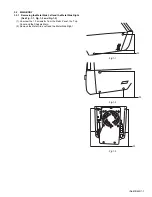
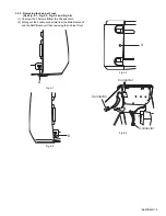
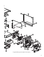
3.3.2 Removing the Main Board and the Power Board
(See Fig.7-1, Fig.7-2, Fig.7-3 and Fig.7-4)
(1) Pulling out the 5 cable connectors from Main Board unit
and the Power Board unit.
(2) Unscrew the 4 screws
G
from the Mechanism Holder.
(3) Separating the Main Board and the Power Board from the
AMP Board vertically.
Fig.7-1
Fig.7-2
Fig.7-3
Fig.7-4
CONNECTOR
CONNECTOR
G
G
Summary of Contents for UX-GD7
Page 1: ......
Page 35: ...2 1 Block diagram ...
Page 37: ...2 3 Amp section ...
Page 38: ...2 4 Function section ...
Page 39: ...2 5 Video section ...
Page 40: ...2 6 Micon section ...
Page 41: ...2 7 Front section ...