86
Applications
To specify settings on camera connection, you first need to add the
required devices, such as network cameras or network encoders
(IP video servers), to the system. Devices have their own IP
addresses and host names. The system identifies the devices
based on their IP address or host name.
Memo :
●
Even though each device is managed using a unique IP address
or host name, in cases such as when multiple analog cameras
are connected to a network encoder (IP video server), a multiple
number of cameras may be connected to a single device and
thus share the same IP address or host name. Although several
cameras are connected to one device in this case, this unit
manages the cameras on an individual basis.
●
In addition to the network camera and network encoder (IP video
server), you can also add a number of dedicated I/O (input/
output) devices to the system. You can configure and use the
event settings for the I/O devices in the same way as cameras.
●
When a device is added to the system, it is listed on the [Camera
Recording Administator] screen. To add a new device, follow the
procedure below. Firstly, configure the IP address and password
of the device according to instructions in the camera manual.
●
You cannot add a camera for which there is user access
restriction. For details on access restrictions, refer to the
camera’s “Instruction Manual”.
●
If the camera is registered with the user access restriction set to
ON, the camera is registered with access restriction and unable
to display live images unless the settings are changed.
1
Select [Camera Record Setting] from the main
menu
2
Click [Add Device...]
●
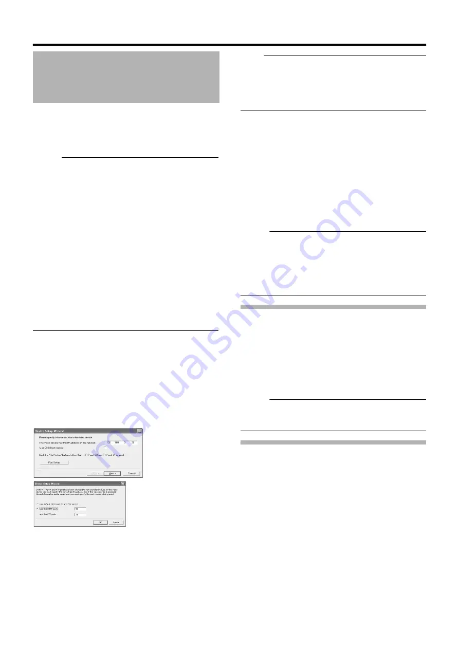
The [Device Setup Wizard] screen appears.
3
Enter the IP address or DNS host name that can
be identified by the system
●
To enter the DNS host name, select the [Use DNS host
name] check box and click [Next].
Note :
●
The
A
http port 80
B
followed by
A
FTP port 21
B
are used by
default. To use a different port, click [Port Setup] and specify the
required port numbers. You may need to specify a different port
if the device is located behind a NAT router or firewall. In this
case, configure the router or firewall so that it maps the ports
and IP address used by the device.
4
If an administrator password is specified for the
device, enter the password
●
The password is usually set to [root] or [admin].
●
Click [Next] without specifying [Autodetect Device].
5
Enter a unique name for the device that has
been detected
●
The device is listed in the [Device Manager].
6
Click [Finish]
●
To view the list of cameras connected to the device, click
the plus (+) sign to the left of the device name.
Memo :
●
The camera names are set as [Camera1], [Camera2],
[Camera3], [Camera4], …etc. by default. To change the name of
a camera, select the device and click the camera name.
●
The camera number increases in sequence as new cameras are
added.
●
Registration of the cameras can also be performed
automatically. (
Page 113 [Auto Detect Settings])
Analog Cameras (VR-N900U)
In VR-N900U, analog input circuitry is considered a network
encoder (IP video server), and the IP address is set to
192.168.201.12.
This is registered as
A
[N900](192.168.201.12)
B
on the Device
Manager of the [Camera Record Setting] screen. Cameras
connected to the [VIDEO IN1 to 4] input terminal at the rear
correspond to Cameras 1 to 4 of
A
N900
B
. You can alter the default
name
A
N900
B
using the [Edit Device...] button. However, the IP
address
A
192.168.201.12
B
cannot be changed.
Memo :
●
Audio signals that are input to [AUDIO IN 1/AUDIO IN 2] on the
rear panel are allocated as [Audio1] and [Audio2] in
[N900](192.168.201.12) on the [Device Manager].
Adding an Analog Camera (VR-N900U)
To add an analog camera manually when using VR-N900U, specify
A
192.168.201.12
B
as the IP address on the [Edit device settings]
screen. As no password has been specified, leave the password
entry field blank and continue to the next step.
Analog cameras are already added on VR-N900U by default.
Adding Cameras
[Device Setup Wizard] Screen
Summary of Contents for LST0728-001C
Page 2: ...IMPORTANT SAFEGUARDS I ...
Page 7: ...VI ...
Page 8: ...SICHERHEITSVORKEHRUNGEN for Germany VII ...
Page 9: ...VIII E VR N900U 1600E VR N900U E VR N900U 1600E VR N900U E VR N900U E VR N900U ...
Page 167: ...159 ...
Page 168: ...LST0728 001C NETWORK VIDEO RECORDER VR N1600U VR N1600E VR N900U ...


