background image

(No.MA150)1-7

SECTION 3

DISASSEMBLY

3.1

Main body section

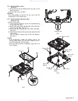
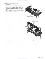
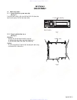
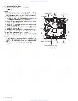
3.1.1 Removing the front panel assembly 

(See Fig.1)

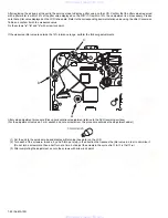
Push the detach button in the lower left part of the front panel as-
sembly and remove the front panel assembly.

Fig.1

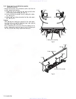
3.1.2 Removing the bottom cover 

(See Fig.2)

Reference:

Remove the front panel assembly as required.
(1) Release the two joints 

a

, two joints 

b

 and joint 

c

.

(2) Remove the bottom cover from the main body.

Caution:

Do not damage the main board when releasing the joints using
a screwdriver or a similar tool.

Fig.2

Front panel assembly

Detach button

Bottom cover

b

b

a

a

c

www. xiaoyu163. com

QQ 376315150

9

9

2

8

9

4

2

9

8

TEL 13942296513

9

9

2

8

9

4

2

9

8

0

5

1

5

1

3

6

7

3

Q

Q

TEL  13942296513  QQ  376315150  892498299 

TEL  13942296513  QQ  376315150  892498299 

http://www.xiaoyu163.com

http://www.xiaoyu163.com

Summary of Contents for KD-DV5105

Page 1: ...ONS 1 6 3 DISASSEMBLY 1 7 4 ADJUSTMENT 1 21 5 TROUBLESHOOTING 1 29 Area suffix A Australia UN Asean KD DV5108 Area suffix UT Taiwan UN Asean U Other Areas KD DV5105 www xiaoyu163 com QQ376315150 9 9 2 8 9 4 2 9 8 TEL 13942296513 9 9 2 8 9 4 2 9 8 0 5 1 5 1 3 6 7 3 Q Q TEL 13942296513 QQ 376315150 892498299 TEL 13942296513 QQ 376315150 892498299 http www xiaoyu163 com http www xiaoyu163 com ...

Page 2: ... µV 75 Ω 50 dB Quieting Sensitivity 16 3 dBf 1 8 µV 75 Ω Alternate Channel Selectivity 400 kHz 65 dB Frequency Response 40 Hz to 15 000 Hz Stereo Separation 35 dB Capture Ratio 1 5 dB AM Tuner Sensitivity 20 µV Selectivity 35 dB DVD CD PLAYER SECTION Signal Detection System Non contact optical pickup semiconductor laser Number of Channels 2 channels stereo Frequency Response DVD fs 48 kHz 96 kHz 1...

Page 3: ...case of preforming repair of this system Please use enough caution not to see the beam directly or touch it in case of an adjustment or operation check www xiaoyu163 com QQ376315150 9 9 2 8 9 4 2 9 8 TEL 13942296513 9 9 2 8 9 4 2 9 8 0 5 1 5 1 3 6 7 3 Q Q TEL 13942296513 QQ 376315150 892498299 TEL 13942296513 QQ 376315150 892498299 http www xiaoyu163 com http www xiaoyu163 com ...
Page 4: ...horted After replacement return the shorted parts to their original condition Refer to the text Do not use a tester to check the condition of the laser diode in the optical pickup The tester s internal power source can easily destroy the laser diode 1 3 Handling the traverse unit optical pickup 1 Before disconnecting the flexible wire from the connector CN101 on the mechanism control board solder ...

Page 5: ...ay result in hazardous radiation exposure REPRODUCTION AND POSITION OF LABELS Please use enough caution not to see the beam directly or touch it in case of an adjustment or operation check WARNING LABEL CAUTION Visible and Invisible laser radiation when open and interlock failed or defeated AVOID DIRECT EXPOSURE TO BEAM e VARNING Synlig och osynling laserstrålning när den öppnas och spärren är urk...

Page 6: ...does not describe SPECIFIC SERVICE INSTRUCTIONS www xiaoyu163 com QQ376315150 9 9 2 8 9 4 2 9 8 TEL 13942296513 9 9 2 8 9 4 2 9 8 0 5 1 5 1 3 6 7 3 Q Q TEL 13942296513 QQ 376315150 892498299 TEL 13942296513 QQ 376315150 892498299 http www xiaoyu163 com http www xiaoyu163 com ...
Page 7: ...mbly as required 1 Release the two joints a two joints b and joint c 2 Remove the bottom cover from the main body Caution Do not damage the main board when releasing the joints using a screwdriver or a similar tool Fig 2 Front panel assembly Detach button Bottom cover b b a a c www xiaoyu163 com QQ376315150 9 9 2 8 9 4 2 9 8 TEL 13942296513 9 9 2 8 9 4 2 9 8 0 5 1 5 1 3 6 7 3 Q Q TEL 13942296513 Q...

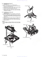
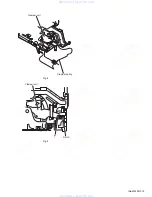
Page 8: ...two joints e See Fig 4 Fig 3 Fig 4 3 1 4 Removing the side heat sink See Fig 5 Reference Remove the front panel and front chassis assemblies as re quired From the left side of the main body remove the two screws C and three screws D attaching the side heat sink Fig 5 A Front chassis assembly d d Front chassis assembly B e e B C D Side heat sink www xiaoyu163 com QQ376315150 9 9 2 8 9 4 2 9 8 TEL 1...

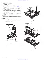
Page 9: ...From the bottom side of the main body remove the three screws J attaching the main board See Fig 7 3 Disconnect the connector CN961 on the main board from the DVD mechanism assembly and take out the main board from the main body See Fig 7 Fig 6 Fig 7 3 1 7 Removing the DVD mechanism assembly See Fig 8 Remove the front panel assembly bottom cover front chassis assembly side heat sink and main board...

Page 10: ...5 Remove the two screws M attaching the main sub board and remove the main sub board from the DVD mechanism assembly See Fig 10 Reference When attaching the main sub board align the joints h in the holes of the main sub board before attaching the screws M See Fig 10 When the resolution of DVD mechanism assembly is done sequentially remove the two screws N attaching the support bracket See Fig 11 R...

Page 11: ... little by little See Fig 14 Reference Remove the volume knob from the front side of the front panel assembly at the same time Note Do not lose the compression springs when removing the switch board See Fig 14 Fig 12 Fig 13 Fig 14 P P Rear cover Front panel assembly P i i Rear cover i i Switch board Front panel assembly Compression spring Compression spring www xiaoyu163 com QQ376315150 9 9 2 8 9 ...

Page 12: ...ire from connector CN202 on the mechanism control board 5 Unsolder two soldered points a on the mechanism control board and remove the wire extending from the feed motor 6 Remove the screw A attaching the lug wire 7 Remove the two screws B and screw C attaching the mechanism control board Caution As the flexible wire to be connected to CN101 make sure to attach it to the mechanism control board us...

Page 13: ...mechanism section upward and remove from the chassis frame The three damper springs come off from the dampers See Fig 4 Caution When reassembling reattach the damper spring to the damper respectively and insert the three shafts on the bot tom of the mechanism to the dampers Before inserting the shaft to the dampers apply IPA to the hole of damper Fig 2 Fig 3 Fig 4 D Top cover Stopper Stopper F F b...

Page 14: ...hassis base assembly Make sure that part g is inserted to the notch of the chassis base assembly See Figs 5 and 9 3 Move the part d of the clamper spring to the outside of the bending part of the chassis base assembly See Fig 7 4 Attach the clamper2 spring to the chassis base assembly See Figs 5 and 6 Caution When reattaching temporarily hook the end of the clamper spring as shown in the figure to...

Page 15: ...ing Notch g Clamper unit www xiaoyu163 com QQ376315150 9 9 2 8 9 4 2 9 8 TEL 13942296513 9 9 2 8 9 4 2 9 8 0 5 1 5 1 3 6 7 3 Q Q TEL 13942296513 QQ 376315150 892498299 TEL 13942296513 QQ 376315150 892498299 http www xiaoyu163 com http www xiaoyu163 com ...

Page 16: ...t unit upward See Figs 11 and 12 4 Remove the two screws H attaching the switch board See Fig 12 Reference You can remove the switch board only without removing the front unit Caution When reassembling attach the flexible wire extending from the switch board using the double tape See Figs 10 and 12 Fig 10 Fig 11 Fig 12 Mechanism control board Flexible wire CN202 Double tape G Front unit h h Front ...

Page 17: ...e assem bly 2 Release the boss from notch n of the connect arm on the right side of the body and release the boss from notch p of the slide cam assembly on the left side Fig 13 Fig 14 k n m Loading arm assembly k n m Loading arm assembly p Side cam assembly Connect arm www xiaoyu163 com QQ376315150 9 9 2 8 9 4 2 9 8 TEL 13942296513 9 9 2 8 9 4 2 9 8 0 5 1 5 1 3 6 7 3 Q Q TEL 13942296513 QQ 3763151...

Page 18: ...roller assem bly attach the rod L and R Attach the rods to the right and left collars of the roller See Fig 15 When reattaching the rod L and R to the loading arm as sembly engage each joint as shown in Fig 15 As joints q of the rod L let the rod through q before reattaching it Fig 15 Fig 16 q q q q q q Rod R Loading arm assembly Rod L Collar Collar Rod R Rod L Roller assembly Washer Collar Collar...

Page 19: ...ch the L S collar to the lead screw and engage joint s See Fig 18 When reattaching the L S collar reattach it to the point s of the lead screw and to the rod M Make sure that the L S collar is set on the rod M spring See Fig 18 4 Remove the screw K attaching the rack spring rack plate on the DVD pickup See Fig 19 5 Pull out the lead screw See Fig 19 Caution Perform adjustment after replacing the p...

Page 20: ...body See Fig 21 2 Remove the two screws M attaching the feed motor as sembly See Fig 21 3 Remove the slit washer from the motor H assembly and pull out the worm wheel See Fig 22 Remove the two screws N attaching the feed motor See Fig 22 Fig 21 Fig 22 L Spindle motor M Feed motor assembly Feed TRI spring Feed motor Motor H assembly Worm wheel Slit washer N www xiaoyu163 com QQ376315150 9 9 2 8 9 4...

Page 21: ...ction method Connection procedure 1 Attach the front chassis assembly to the main board 2 Connect the front panel assembly to the main board 3 Attach the heat sink and rear bracket to the main board 4 Attach the extension studs to the DVD mechanism assembly 5 Connect the DVD mechanism assembly and the main board with a extension cable Power supply voltage DC14 4V 11 to 16V Load impedance 4Ω 2 Spea...

Page 22: ...ent procedure Pickup horizontal level adjustment relative to the DVD recording surface For the adjustment tool use a 3 mm wrench and not a screwdriver this procedure will make the adjustment easier 1 Set the unit to the service mode and display a jitter value hex data on the LCD 2 Turn each of the screws a b and c by a half turn per step in the direction that reduces the jitter value in order to m...

Page 23: ... 1801 04 1798 38 1795 72 1793 06 1790 4 1787 74 1785 08 1782 42 1779 76 1777 1 1774 44 1771 78 1769 12 1766 46 1763 8 1761 14 1758 48 Jitter value 8 5 8 6 8 7 8 8 8 9 9 0 9 1 9 2 9 3 9 4 9 5 9 6 9 7 9 8 9 9 10 0 10 1 10 2 10 3 10 4 10 5 10 6 10 7 10 8 10 9 11 0 11 1 11 2 11 3 11 4 11 5 11 6 11 7 11 8 11 9 12 0 12 1 12 2 3A11 3A1E 3A2C 3A39 3A46 3A54 3A61 3A6E 3A7B 3A89 3A96 3AA3 3AB1 3ABE 3ACB 3AD...

Page 24: ...ially 3 This unit is set by a service mode Exchanging it operate a menu of a service mode with the DISC UP button and DISC DOWN button Operate choice of a menu with a SEL button Power supply voltage DC14 4V 11 to 16V Load impedance 4Ω 2 Speakers connection Line Output 20KΩ SEL button STANDBY ON ATTENUATOR button SOURCE button DISC UP button DISC DOWN button www xiaoyu163 com QQ376315150 9 9 2 8 9 ...

Page 25: ...n area region display Press the SEL key VIDEO is indicated on the LCD Setting of NTSC or PAL NTSC or PAL are indicated on the LCD Exchanging it operate each indication with the DISC UP button and DISC DOWN button Press the SEL key CLR ERR is indicated on the LCD Clear loading ejection error history The error history stored in the EEPROM is cleared Exchanging it operate each indication with the DIS...

Page 26: ...oad start Load completion Route No EJECT route No 1 2 1 2 2 2 2 2 3 1 3 1 Chart 1 2 8cm Disc switch status transition SW1 2 3 4 1 1 1 1 0 1 1 1 0 0 1 1 0 1 1 1 1 1 1 1 1 1 1 0 1 1 1 0 Rest SW 0 0 0 0 0 0 1 Loading No Disc Disc insert detection Load completion Eject No Disc Eject completion Eject start Reload Disc push in Reload start Load completion Transition in the center loading Similar to 12cm...

Page 27: ...eck mode See section 5 1 4 DVD unit check mode for details Press the SEL key SYS TEMP is indicated on the LCD Thermistor s temperature data readout Data in the temperature sensor in the system control is read every 5 seconds and displayed in hex numbers Press the SEL key RUNNING is indicated on the LCD Running mode For use in running tests www xiaoyu163 com QQ376315150 9 9 2 8 9 4 2 9 8 TEL 139422...

Page 28: ... PLAY CUR JIT STOP DSC OPEN Laser current value Jitter value For EF phase error For EF phase error Laser current value Jitter value Laser current value Jitter value Laser current value Jitter value EEPROM address EEPROM contents Temperature Position measured with VT 501 Jitter value Laser current value Jitter value No A D key DVD unit operation Example of LCD indication Indication contents Press k...

Page 29: ...NG REMOTE OUT POWER ANTENNA BK RD BL WH BR Black Red Blue White Brown GN Green VI Violet GY Gray YL Yellow OR Orange YG Yellow Green RR Rear Right FR Front Right FL Front Left RL Rear Left REMOTE Remote ILL Illuminations Control ANT ACC TEL Auto Antenna ACC Line Telephone Muting GND Ground MEMORY Memory Backup Battery PARKING Parking Brake 13 BR TEL www xiaoyu163 com QQ376315150 9 9 2 8 9 4 2 9 8 ...

Page 30: ...y 371 8543 Japan Victor Company of Japan Limited VPT Printed in Japan www xiaoyu163 com QQ376315150 9 9 2 8 9 4 2 9 8 TEL 13942296513 9 9 2 8 9 4 2 9 8 0 5 1 5 1 3 6 7 3 Q Q TEL 13942296513 QQ 376315150 892498299 TEL 13942296513 QQ 376315150 892498299 http www xiaoyu163 com http www xiaoyu163 com ...
Page 31: ... Taiwan UN Asean U Other Areas KD DV5105 Contents Block diagram Standard schematic diagrams Printed circuit boards 2 1 2 2 2 5 to 7 CD ROM No SML200502 www xiaoyu163 com QQ376315150 9 9 2 8 9 4 2 9 8 TEL 13942296513 9 9 2 8 9 4 2 9 8 0 5 1 5 1 3 6 7 3 Q Q TEL 13942296513 QQ 376315150 892498299 TEL 13942296513 QQ 376315150 892498299 http www xiaoyu163 com http www xiaoyu163 com ...
Page 32: ...em Safety precaution Please use enough caution not to see the beam directly or touch it in case of an adjustment or operation check www xiaoyu163 com QQ376315150 9 9 2 8 9 4 2 9 8 TEL 13942296513 9 9 2 8 9 4 2 9 8 0 5 1 5 1 3 6 7 3 Q Q TEL 13942296513 QQ 376315150 892498299 TEL 13942296513 QQ 376315150 892498299 http www xiaoyu163 com http www xiaoyu163 com ...
Page 33: ... Q641 DIMMER CONT DIM_CON CN962 CN963 CN961 IC161 E VOLUME DVDL DVDR CN141 LINE L LINE R LINE IN Main amplifier section Tu L Tu R CN701 J801 CHL CHR CHANGER SCK SI SO IC801 JVC BUS BUSSO BUSSCK BUSINT I O SI SO KEY0 to KEY2 DIMOUT LCDCL LCDDA LCDCE ENC1 ENC2 REMOCON IC721 CPU S METER IFCCONT SD ST VOLDA VOLCK VOLMUTE SACLK SAOUT KEY0 to KEY2 DIMOUT LCDCL LCDDA LCDCE ENC1 ENC2 REMOCON BUSSO BUSSCK ...

Page 34: ...1 004X UN2211 X UN2111 X MA111 X 10 16 10 39K UN2211 X KTD1304 X 2SD1994A RS T 470 QGA2001C1 02 10 UN2211 X 10k 330 6 3 MA111 X UDZS5 1B X SN74LVC32APW X 0 0 1K 100k UDZS5 1B X 2 2 50 2 2 50 UDZS5 1B X UDZS5 1B X 0 47 QGA2501C3 03Z 100P 9 1K 1k 2 2 50 2 2k KTD1304 X KTD1304 X KTD1304 X KTD1304 X 2 2k 2 2k 2 2k 2 2k 100 100 100 100 470 0 0 MA111 X 100 16 UDZS11B X UN2111 X 2 2 50 TB2118F X 22 16 BR...

Page 35: ...1 270 UDZS5 1B X 470 330 470 390 1 2K 1 2K 0 047 1 2K 1 2K MA8062 M X 1k 51k 680p 10k 10k 10k 390 470 47k NSPW310BS BRS NSPW310BS BRS 2SB624 4 X 470 10K 0 0 330 390 KEY0 KEY1 REMOCON KEY2 ENC1 KEY1 LCDDA DIM_CON KEY0 LCDCL GND DIMOUT LCDCE S17 ENC2 S18 KEY2 AUX R AUX L AUX GND 10V S19 S20 S21 S22 S23 S24 S25 S26 S27 S28 S29 S30 S31 S32 ENC1 LCDDA S3 LCDCL S4 S5 S6 LCDCE S7 S8 S9 S10 S50 S2 S11 S1 ...

Page 36: ...200 4 7K 3300P 470P 47 10 0 1 16 DGND 10 22k 22k 0 1 16 0 1 16 NI M5V BA5835FM X 1k M9V 0 0 30k 0 1 16 47k 27k 27k 0 0 22k 20k 680p 560p NI 270p 150p 18k 15k 0 022 10k 10k NI 2 7k DTC114EE X NI 15k D5V NI NQR0022 005X DGND MGND M9V D5V M5V S5V S3 3V DGND D3 3V DGND NQR0022 005X NQR0022 005X NQR0022 005X NQR0022 005X NQR0022 005X NQR0022 005X NQR0022 005X NQR0022 005X NQR0022 005X NQR0022 005X 0 NQ...

Page 37: ...761 R762 R763 R765 R766 R767 R768 R769 R770 R771 R772 R773 R774 R775 R776 R777 R778 R801 R802 R803 R804 R805 R806 R807 R808 R809 R810 R841 R842 R843 R844 R881 R882 R883 R885 R886 R887 R888 R889 R901 R902 R903 R905 R906 R907 R909 R910 R914 R921 R923 R924 R925 R926 R927 R928 R929 R961 R973 R974 R975 R976 R977 RA31 RA721 RA723 S701 S702 S723 TH721 TU21 W21 X31 X71 X721 X722 PP1 D719 CN961 A PP2 PP3 B...

Page 38: ...02 IC401 IC411 K102 K301 K399 K401 K402 K403 K404 K405 K406 K407 K426 K430 K431 K433 K441 K444 K445 K451 K452 L301 L451 Q101 Q102 Q103 Q104 Q105 Q231 Q301 R101 R103 R104 R105 R106 R107 R108 R109 R110 R111 R112 R113 R114 R115 R116 R117 R118 R125 R126 R201 R231 R232 R251 R253 R255 R303 R305 R310 R312 R313 R314 R315 R316 R321 R322 R326 R327 R328 R329 R330 R331 R340 R341 R342 R344 R345 R346 R347 R348 ...

Page 39: ...92 R393 R394 R396 R397 R398 R399 R401 R402 R403 R404 R411 R421 R521 R601 R602 REST SBRK SPDRV SW1 SW2 SW3 SWGND TDRV C367 TP1 TP2 TP3 TP4 TP5 TP6 TP7 TP8 TP9 TP10 TP11 TP12 TP14 TP15 TP16 TP17 TP18 TP19 TP20 TP21 TP22 TP24 TP26 TP28 TP29 TP31 TP32 TP33 TP34 TP35 TP36 TP37 TP38 TP39 TP40 TP41 TP51 TP52 TP201 TP202 TP302 TP303 C368 TP306 TP307 TP308 TP309 TP312 TP313 TP314 TP315 TP316 TP317 TP318 TP...

Page 40: ...tari machi Maebashi city 371 8543 Japan Victor Company of Japan Limited www xiaoyu163 com QQ376315150 9 9 2 8 9 4 2 9 8 TEL 13942296513 9 9 2 8 9 4 2 9 8 0 5 1 5 1 3 6 7 3 Q Q TEL 13942296513 QQ 376315150 892498299 TEL 13942296513 QQ 376315150 892498299 http www xiaoyu163 com http www xiaoyu163 com ...
Page 41: ...Block No 01 03 Packing materials and accessories parts list Block No M3 KD DV5105 KD DV5108 3 2 3 6 3 9 3 16 Area suffix KD DV5105 UT Taiwan UN Asean U Other Areas Area suffix KD DV5108 A Australia UN Asean MA150 www xiaoyu163 com QQ376315150 9 9 2 8 9 4 2 9 8 TEL 13942296513 9 9 2 8 9 4 2 9 8 0 5 1 5 1 3 6 7 3 Q Q TEL 13942296513 QQ 376315150 892498299 TEL 13942296513 QQ 376315150 892498299 http ...
Page 42: ... 19 67 5 17 6 18 7 56 58 65 55 59 85 48 54 15 1 53 40 41 50 42 38 24 34 26 39 37 30 22 33 36 29 35 27 28 25 23 31 13 only KD 45 www xiaoyu163 com QQ376315150 9 9 2 8 9 4 2 9 8 TEL 13942296513 9 9 2 8 9 4 2 9 8 0 5 1 5 1 3 6 7 3 Q Q TEL 13942296513 QQ 376315150 892498299 TEL 13942296513 QQ 376315150 892498299 http www xiaoyu163 com http www xiaoyu163 com ...

Page 43: ...77 78 72 10 71 73 81 82 83 61 60 62 64 63 9 9 84 80 8 8 3 11 87 only KD DV5105_UT www xiaoyu163 com QQ376315150 9 9 2 8 9 4 2 9 8 TEL 13942296513 9 9 2 8 9 4 2 9 8 0 5 1 5 1 3 6 7 3 Q Q TEL 13942296513 QQ 376315150 892498299 TEL 13942296513 QQ 376315150 892498299 http www xiaoyu163 com http www xiaoyu163 com ...

Page 44: ...0 008A FRONT PANEL ASSY DV5108A DV5108UN 41 GE31592 005A FINDER ASSY DV5105U DV5105UN DV5105UT 41 GE31592 006A FINDER ASSY DV5108A DV5108UN 42 GE40254 004A VOLUME KNOB ASS DV5105U DV5105UN DV5105UT 42 GE40254 005A VOLUME KNOB ASS DV5108A DV5108UN 43 GE31599 001A RIM LENS 44 GE31593 008A D FUNC BUTTON DV5105U DV5105UN DV5105UT 44 GE31593 001A D FUNC BTN DV5108A DV5108UN 45 GE20175 005A PRESET BUTTO...

Page 45: ...SCREW M2 6 x 4mm x2 76 QYSDST2604ZA TAP SCREW M2 6 x 4mm 77 QYSDST2606ZA TAP SCREW M2 6 x 6mm 78 QYSDSF3008ZA TAP SCREW M3 x 8mm 79 QYSDSF3008ZA TAP SCREW M3 x 8mm 80 QYSDST2604ZA TAP SCREW M2 6 x 4mm 81 LV43349 002A POWER IC BKT 82 LV43373 002A REGULATOR BKT 83 GE40270 001A SHIELD COVER 84 VMA4652 001SS EARTH PLATE 85 GE30854 001A LED HOLDER 86 VYTA500 001 PIN CAP x2 87 GE31574 014A UT LABEL DV51...

Page 46: ...31 34 24 22 37 38 19 88 90 87 89 64 40 43 39 41 42 65 43 33 47 44 46 45 49 48 50 51 62 56 54 53 55 52 63 10 12 8 5 10 11 9 5 12 10 8 17 16 13 16 17 4 77 78 67 69 68 66 86 84 85 70 2 1 1 82 86 81 80 86 79 76 83 72 73 71 26 3 74 20 21 75 58 59 61 60 57 3 23 25 BACK SIDE 6 7 INSIDE 98 www xiaoyu163 com QQ376315150 9 9 2 8 9 4 2 9 8 TEL 13942296513 9 9 2 8 9 4 2 9 8 0 5 1 5 1 3 6 7 3 Q Q TEL 139422965...

Page 47: ...A WORM GEAR 39 QYSPSPT2025M SCREW M2 x 2 5mm x2 40 LV33679 001A MOTOR H ASSY 41 LV33614 002A WORM WHEEL 42 QYWDL1230250 SLIT WASHER 3mm 1 2mm x 0 25mm 43 VKZ4539 026 MINI SCREW x2 44 LV33615 001A GEAR 2 45 LV43057 003A IDLER ARM ASSY 46 QYWDL1635252 SLIT WASHER 3 5mm 1 6mm x 0 25mm 47 LV21286 001A CONTROL CAM 48 QYWDL1230250 SLIT WASHER 3mm 1 2mm x 0 25mm 49 LV33616 001A LOAD LOCK LEVER 50 LV43060...

Page 48: ...88 LV43070 001A CLAMPER SPRING 89 LV43355 001A CLAMPER2 SPRING 90 LV30225 0J6A SPACER 91 LV21299 006A FRONT UNIT 92 VKZ4539 026 MINI SCREW 93 LVB30012 001A SW FPC 94 NSW0187 001 SWITCH 95 NSW0187 001 SWITCH 96 NSW0187 001 SWITCH 97 VKZ4539 025 MINI SCREW x2 98 LV44232 001A GRAPHITE SHEET Symbol No Part No Part Name Description Local www xiaoyu163 com QQ376315150 9 9 2 8 9 4 2 9 8 TEL 13942296513 9...

Page 49: ...Z E CAPACITOR 0 1uF 50V M C28 NCS31HJ 7R0X C CAPACITOR 7pF 50V J C29 NDC31HJ 100X C CAPACITOR 10pF 50V J C30 NDC31HJ 100X C CAPACITOR 10pF 50V J C31 NCB31HK 103X C CAPACITOR 0 01uF 50V K C32 NCB31HK 103X C CAPACITOR 0 01uF 50V K C33 NCB31HK 102X C CAPACITOR 1000pF 50V K C34 NCB31HK 103X C CAPACITOR 0 01uF 50V K C35 QFV61HJ 473Z MF CAPACITOR 0 047uF 50V J C36 NCB31HK 102X C CAPACITOR 1000pF 50V K C...

Page 50: ...l C981 NCB31CK 104X C CAPACITOR 0 1uF 16V K C997 NCB31HK 103X C CAPACITOR 0 01uF 50V K C999 NCS31HJ 101X C CAPACITOR 100pF 50V J R1 NRSA63J 473X MG RESISTOR 47kΩ 1 16W J R2 NRS181J 220X MG RESISTOR 22Ω 1 8W J R3 NRS181J 220X MG RESISTOR 22Ω 1 8W J R4 NRSA63J 473X MG RESISTOR 47kΩ 1 16W J R5 NRSA63J 472X MG RESISTOR 4 7kΩ 1 16W J R6 NRSA63J 332X MG RESISTOR 3 3kΩ 1 16W J R7 NRSA63J 473X MG RESISTOR...

Page 51: ...470Ω 1 16W J R784 NRSA63J 222X MG RESISTOR 2 2kΩ 1 16W J R799 NRSA63J 222X MG RESISTOR 2 2kΩ 1 16W J Symbol No Part No Part Name Description Local R801 NRSA63J 101X MG RESISTOR 100Ω 1 16W J R802 NRSA63J 473X MG RESISTOR 47kΩ 1 16W J R803 NRSA63J 223X MG RESISTOR 22kΩ 1 16W J R804 NRSA63J 104X MG RESISTOR 100kΩ 1 16W J R805 NRSA63J 103X MG RESISTOR 10kΩ 1 16W J R806 NRSA63J 104X MG RESISTOR 100kΩ 1...

Page 52: ... MG RESISTOR 1 2kΩ 1 16W J R632 NRSA63J 122X MG RESISTOR 1 2kΩ 1 16W J R633 NRSA63J 122X MG RESISTOR 1 2kΩ 1 16W J R634 NRSA63J 271X MG RESISTOR 270Ω 1 16W J R636 NRSA63J 271X MG RESISTOR 270Ω 1 16W J R638 NRSA63J 471X MG RESISTOR 470Ω 1 16W J R640 NRSA02J 331X MG RESISTOR 330Ω 1 10W J R641 NRSA02J 391X MG RESISTOR 390Ω 1 10W J R642 NRSA02J 331X MG RESISTOR 330Ω 1 10W J R643 NRSA02J 391X MG RESIST...

Page 53: ...321 NCB31CK 104X C CAPACITOR 0 1uF 16V K C322 NCB31CK 104X C CAPACITOR 0 1uF 16V K C323 NCB31CK 104X C CAPACITOR 0 1uF 16V K C324 NCB21CK 105X C CAPACITOR 1uF 16V K C325 NDC31HJ 100X C CAPACITOR 10pF 50V J C326 NDC31HJ 100X C CAPACITOR 10pF 50V J C330 NCB31CK 104X C CAPACITOR 0 1uF 16V K C331 NCB31CK 333X C CAPACITOR 0 033uF 16V K C332 NCB31CK 104X C CAPACITOR 0 1uF 16V K C333 NCB31CK 104X C CAPAC...

Page 54: ...RESISTOR 47kΩ 1 16W J Symbol No Part No Part Name Description Local R350 NRSA63J 750X MG RESISTOR 75Ω 1 16W J R351 NRSA63J 102X MG RESISTOR 1kΩ 1 16W J R352 NRSA63J 105X MG RESISTOR 1MΩ 1 16W J R353 NRSA63J 101X MG RESISTOR 100Ω 1 16W J R354 NRSA63J 101X MG RESISTOR 100Ω 1 16W J R355 NRSA63J 0R0X MG RESISTOR 0Ω 1 16W J R356 NRSA63J 0R0X MG RESISTOR 0Ω 1 16W J R357 NRSA63J 0R0X MG RESISTOR 0Ω 1 16W...

Page 55: ...ADS K443 NQR0022 005X FERRITE BEADS K444 NQR0022 005X FERRITE BEADS K445 NQR0022 005X FERRITE BEADS K451 NQR0022 005X FERRITE BEADS K452 NQR0022 005X FERRITE BEADS K601 NQR0022 005X FERRITE BEADS SW4 NSW0184 001X DETECT SW SW5 NSW0183 001X DETECT SW TH491 NAD0025 103X N THERMISTOR 10kΩ X351 NAX0730 001X CRYSTAL Symbol No Part No Part Name Description Local www xiaoyu163 com QQ376315150 9 9 2 8 9 4...

Page 56: ...N P3 P4 P8 P7 A11 A15 A5 A6A7 A8 A13 A12 A9A10 A14 KD DV5105_U KD DV5108_A KD DV5105_U KD DV5108_A A4 A3 www xiaoyu163 com QQ376315150 9 9 2 8 9 4 2 9 8 TEL 13942296513 9 9 2 8 9 4 2 9 8 0 5 1 5 1 3 6 7 3 Q Q TEL 13942296513 QQ 376315150 892498299 TEL 13942296513 QQ 376315150 892498299 http www xiaoyu163 com http www xiaoyu163 com ...
Page 57: ... 11 FSJB3002 30C HARD CASE A 12 RM RK230 REMOTE CONTROL A 13 BATTERY A 14 QAM0455 002 CAR CABLE A 15 GET0278 002A INST BOOK DV5105U DV5108A A 16 GET0278 005A INSTALL MANUAL DV5105U DV5108A KIT SRW DV5100J SCREW PARTS KIT A5 A6 A7 A8 A9 A10 P 1 GE31513 001A CARTON DV5105U DV5105UN DV5105UT P 1 GE31516 001A CARTON DV5108A P 1 GE31747 001A CARTON DV5108UN P 2 QPC03004315P POLY BAG 30cm x 43cm P 3 FSP...

Reviews: