(No.86733)1-13
2.5 ASSEMBLY AND DISASSEMBLY OF [10]MONITOR ASSEMBLY (CABINET PARTS)
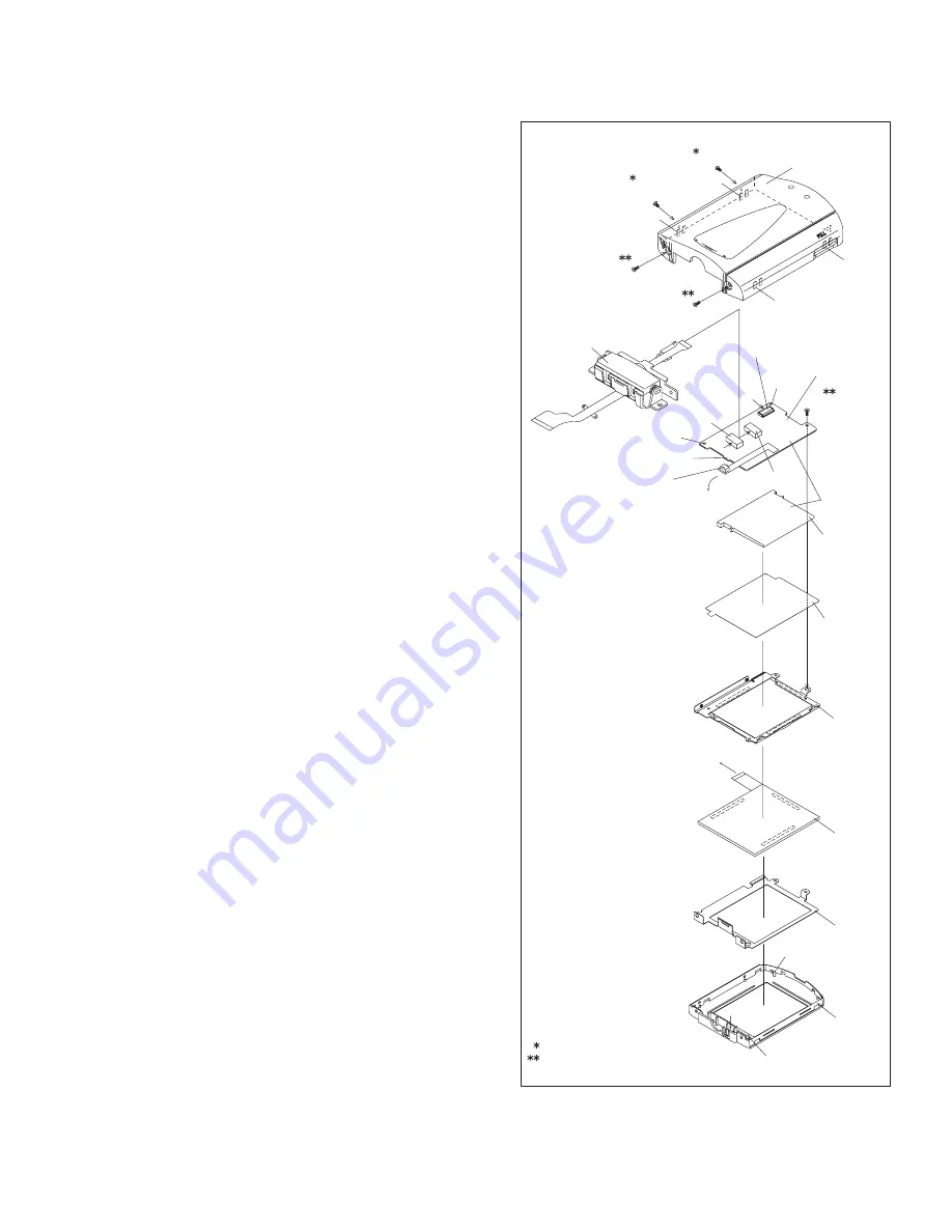
2.5.1 Disassembly of MONITOR ASSEMBLY (2.5 INCH)
NOTE:
Be careful in removing or handling the monitor assembly, es-
pecially not to soil or scratch the monitor screen during the dis-
assembly procedure.
(1) While removing the four screws (1 to 4) in numerical order
and then disengaging the four hooks (L10a-L10d) in alpha-
betical order, open and remove the MONITOR COVER
ASSEMBLY.
(2) Remove the SENSOR BOARD ASSEMBLY from the
MONITOR CASE.
(3) Disconnect the FPC in the connectors CN10a and CN10b
in this order, and then remove the MONI.HINGE ASSEM-
BLY.
(4) Disconnect the FPC of the LCD MODULE from the connec-
tor CN10c.
(5) Remove one screw (5) and then remove the BL BOARD
ASSEMBLY together with the BACK LIGHT ASSEMBLY.
NOTE 10a:
It depends on the inch size of the monitor assembly
whether the backlight is supplied as an assembly or as
separated parts.
In replacing the backlight assembly, see the Parts List.
NOTE 10b:
Since the BACK LIGHT ASSEMBLY is soldered to the
BL BOARD ASSEMBLY, the BACK LIGHT should not be
separated from the BL BOARD ASSEMBLY except
when replacing them.
(6) Remove the DIFF.SHEET.
(7) Remove the LCD FRAME together with the LCD MODULE.
(8) Remove the SHIELD CASE.
Fig.2-5-1
DIFF. SHEET
NOTE10a
BACK LIGHT
NOTE10b
BL-2.5 BOARD
ASSEMBLY
MONITOR
CASE
L10g
SHIELD CASE
L10f
5
(S10a)
L10b
CN10b
SD10b
SD10a
L10e
CN10a
CN10c
L10a
L10d
L10c
MONITOR COVER
ASSEMBLY
4
(S10b)
3
(S10b)
1
(S10a)
2
(S10a)
b
LCD FRAME
LCD MODULE
c
b
MONI.HINGE
ASSEMBLY
SENSOR BOARD
ASSEMBLY
:0.069N
.
m (0.7kgf
.
cm)
:0.098N
.
m (1.0kgf
.
cm)
a
a
c


