


CCD
2
0
5007
(Bottom View)
5001
5001
5001
5005
5003
CN
IC
Q
C
R
VACANT No
LAST No
TP5002
TP5001
OPEN
R5002
OPEN
R5003
0Ω
R5004
OPEN
4.7k
R5001
OPEN
3
2
1
2SC3931/CD/-X
Q5001
V4
1
V3
2
V2
3
V1
4
GN
D
5
GN
D
6
VOUT
7
VD
D
8
RG
9
SU
B
10
VL
11
H1
12
H2
13
RCSUB
14
(1/6 Inch_CCD)
ICX641UKM-V
IC5001
GND
22
GND
21
H1
20
H2
19
SUB
18
RG
17
CCD_CTL
16
V6
15
V5
14
V4
13
V3
12
V2
11
V1
10
REG-CCD
9
REG+CCD
8
GND
7
GND
6
GND
5
CCD_OUT
4
GND
3
GND
2
GND
1
CN5001
QGF0543F3-22X
OPEN
C5004
OPEN
C5002
OPEN
C5003
0.1
C5006
0.0022
C5007
1
C5001
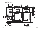
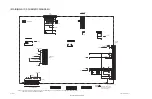
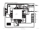
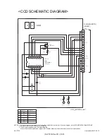
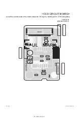
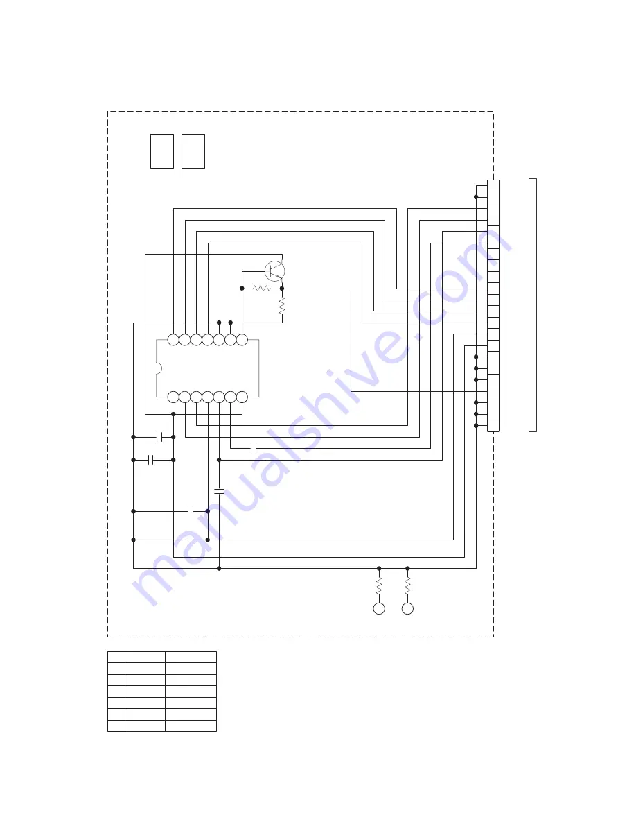
<CCD SCHEMATIC DIAGRAM>
yf335_y40278001a_ver0.1
When IC5001 needs replacement, replace the CCD base assembly in whole because it cannot be replaced alone.
3. IC5001 is incorporated in the CCD base assembly .
2. Be sure to check the PARTS LIST for availability.
NOTES: 1. For the destination of each signal and further line connections that are cut off from this diagram, refer to "BOARD INTERCONNECTIONS".
(CN4201)
To MAIN(AEF/TG)
created date:2010-02-19
No.YF335
(No.YF335<Rev.001>)14/30