background image

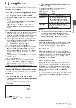
About the Operation Lock

Feature (KEYLOCK)

You can use this feature to prevent erroneous

camera operation.

.

1

Set the [KEYLOCK] switch to “ON”.

0

The operation lock turns on, and an operation

lock icon (

r

) appears on the display

screen.

0

The operation lock function is turned off when

the [KEYLOCK] switch is set to “OFF”.

Memo : 

0

The operation lock feature is only valid in the

Camera mode.

(

A

 P24 [Operation Modes] )

0

The following remote operations are possible

even when the operation lock feature is turned

on (“On”).

0

Remote operation from the wired remote

control connected to the [REMOTE] terminal.

0

Remote operation of the camera through

access via a browser on devices such as a

smartphone, tablet terminal, or PC.

Operation lock does not apply to the following

buttons and switches.

0

[POWER ON/OFF] switch

0

[ND FILTER] switch

0

[TC IN/OUT] switch

0

Focus Ring

0

Zoom Ring

0

Iris Ring

0

Zoom Lever at the Grip

0

Zoom Lever on Handle

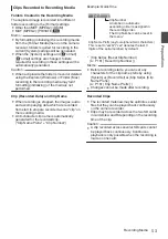
0

[FIX/VAR/OFF] switch

Memo : 

0

Operation lock does not apply to the REC button

if “Keylock Except Rec” is selected in [Camera

Function]


B


[KEYLOCK].

(

A

 P113 [ KEYLOCK ] )

54

About the Operation Lock Feature (KEYLOCK)

Preparations

Summary of Contents for Connected Cam GY-HC500E

Page 1: ...iPhone http manual3 jvckenwood com pro mobile global You can view the Mobile User Guide using the browser on your Android phone or iPhone Thank you for purchasing this product Before operating this unit please read the instructions carefully to ensure the best possible performance In this manual each model number is described without the last letter U E which means the shipping destination U for U...

Page 2: ...2 ...

Page 3: ...plifiers that produce heat Protect the power cord from being walked on or pinched particularly at plugs convenience receptacles and the point where they exit from the apparatus Only use attachments accessories specified by the manufacturer Use only with the cart stand tripod bracket or table specified by the manufacturer or sold with the apparatus When a cart is used use caution when moving the ca...

Page 4: ...qu avec le chariot le stand le trépied le support ou la table spécifié par le fabricant ou vendu avec l appareil Lorsqu un chariot est utilisé faire attention pour déplacer la combinaison chariot appareil pour éviter des blessures causées par un basculement Débrancher cet appareil pendant un orage ou quand il n est pas utilisé pendant une longue durée L entretien ou la réparation de l appareil doi...

Page 5: ...ing the appliance RISK OF ELECTRIC SHOCK DO NOT OPEN POUR CANADA RISQUE D ELECTROCUTION NE PAS OUVRIR ATTENTION POUR EVITER TOUT RISQUE D ELECTROCUTION NE PAS OUVRIR LE BOITER AUCUNE PIECE INTERIEURE N EST A REGLER PAR L UTILISATEUR SE REFERER A UN AGENT QUALIFIE EN CAS DE PROBLEME ATTENTION Le symbole de l éclair à l intérieur d un triangle équilatéral est destiné à alerter l utilisateur sur la p...

Page 6: ...marque Personne responsable Adresse Numéro de téléphone Déclaration de conformité du fournisseur GY HC550U GY HC500U GY HC500SPCU JVC JVCKENWOOD USA Corporation 500 Valley Road Suite 203 Wayne NJ 07470 973 317 5000 Cet ensemble se conforme à la partie 15 des règles de la FCC Federal Communications Commission Le fonctionnement est sujet aux deux conditions suivantes 1 Cet appareil ne peut pas cause...

Page 7: ...ationnelle Débranchez immédiatement la fiche secteur si le caméscope ne fonctionne pas normalement Avertissement Évitez d exposer la batterie le caméscope avec la batterie insérée ou la télécommande avec la batterie insérée à une chaleur excessive telle que celle des rayons directs du soleil d un feu ou de tout autre source de chaleur AVERTISSEMENT POUR EVITER LES RISQUES D INCENDIE OU D ELECTROCU...

Page 8: ...dans un coffret ou sur une étagère s assurer qu il y a un espace suffisant sur tous les côtés pour permettre la ventilation 10 cm 3 15 16 ou plus sur les deux côtés au dessus et à l arrière Ne pas boucher les orifices de ventilation Si les orifices de ventilation sont bouchés par un journal un tissu etc la chaleur peut ne pas s éliminer Aucune source à flamme nue telle que des bougies allumées ne ...

Page 9: ...ission L EME par RF énergie électrique et magnétique par radiofréquences peut causer de légers effets thermiques ou chauffants sur toute partie de votre corps lorsque vous trouvez à une distance inférieure à cellerecommandéedel antennedecetémetteur radio L exposition à l énergie par radiofréquences est principalement déterminée par la distance et la puissance de l appareil émetteur En général l ex...

Page 10: ...Hz 50 Ω 1 9 dBi 2 4 2 5 GHz Pour usage intérieur seulement 5150 5250 MHz au Canada Il existe des restrictions légales concernant l utilisation générale et extérieure en fonction du pays et de la région Veillez à respecter la loi La transmission des données est toujours initiée par le logiciel puis les données sont transmises par l intermédiaire du MAC par la bande de base numérique et analogique e...

Page 11: ...e antenne ou un autre émetteur L émetteur récepteurexemptdelicencecontenu dans le présent appareil est conforme aux CNR d Innovation Sciences et Développement économique Canada applicables aux appareils radio exempts de licence L exploitation est autorisée aux deux conditions suivantes A L appareil ne doit pas produire de brouillage B L appareil doit accepter tout brouillage radioélectrique subi m...

Page 12: ...lack Brown to L Live or Red WARNING Operation of this equipment in a residential environment could cause radio interference CAUTION Where there are strong electromagnetic waves or magnetism for example near a radio or TV transmitter transformer motor etc the picture and the sound may be disturbed In such case please keep the apparatus away from the sources of the disturbance The plastics packaging...

Page 13: ... Battery Pack The supplied battery pack is a lithium ion battery Before using the supplied battery pack or an optional battery pack be sure to read the following cautions To avoid hazards do not burn When transporting carry the battery in a plastic bag do not modify or disassemble do not expose the battery to temperatures exceeding 60 C 140 F as this may cause the battery to overheat explode or ca...

Page 14: ...ateria velha ao comerciante ou para a rede autorizada para que seja devolvida ao fabricante ou importador A reciclagem e eliminação de lixo em uma maneira adequada ajudarão para preservar recursos prevenindo ao mesmo tempo contra efeitos prejudiciais sobre a nossa saúde e o meio ambiente o Empurre 14 Safety Precautions Introduction ...

Page 15: ...50 Removing the SD Card 50 Switching the SD cards 51 Inserting the SSD Media Adapter 51 Formatting Initializing of Recording Media 51 Repairing the Recording Media 52 Clips Recorded to Recording Media 53 About the Operation Lock Feature KEYLOCK 54 Shooting Basic Shooting Procedures 55 Selecting System Definition File Format and Video Format 56 Zoom Operation 59 Focus Operation 60 Adjusting the Foc...

Page 16: ...s Favorites Menu 162 Adding Menu Items to Favorites Menu 162 Editing Favorites Menu 163 Display Status Screen Display Screen in Camera Mode 166 Display Screen in Media Mode 172 Status Screen 174 Camera Features Marker and Safety Zone Displays Camera Mode Only 176 Color Bar Output 176 Adjusting the Gamma 177 Adjusting Color Matrix 178 Configuring Setup Files 179 Saving Setup Files 180 Loading a Set...

Page 17: ...L 229 Configuring to Exchange Format 229 Configuring Camera Angle Information 229 Entering Tag Information 229 Synchronizing GPS Time Code 230 Overlay A L Broadcast Overlay A L 231 Importing and Configuring Settings for SDP Files for Broadcast 231 Displaying Watermark Images 233 Displaying Images on the Whole Screen Full Screen Graphic Function 233 Protecting Overlay Settings with a Password 235 S...

Page 18: ...422HQ Apple ProRes 422 and Apple ProRes 422LT Selectable MPEG 4 AVC H 264 formats include QuickTime MOV and MP4 It is also compatible with MPEG2 MXF which is a widely used format at broadcasting stations A HDR and log gamma for high dynamic range and wide color gamut This camera recorder is equipped with HLG Hybrid Log Gamma that conforms to ITU BT 2100 and our in house J Log1 Gamma with 800 dynam...

Page 19: ...mbols used Caution Describes precautions concerning the operation of this product Memo Describes reference information such as functions and usage restrictions of this product A Indicates the reference page numbers and reference items A Feature available on GY HC550U GY HC550E only B Feature available on GY HC500U GY HC500E GY HC500SPCU only L Feature available on GY HC500SPCU only Content of this...

Page 20: ...ooting on a beach In addition salt and sand may adheretothebody Besuretocleantheunitafter use o Protect this unit against penetration of dust when using it in a place subject to sandy dust Carrying the Camera o Do not drop or hit this unit against a hard object when transporting Power Saving o When this unit is not in use be sure to set the POWER ON OFF switch to OFF in order to reduce power consu...

Page 21: ... of data stored on the SD card Please back up any important data o Make use of the SD card within the prescribed conditions of use Do not use it at the following locations Places that are subject to direct sunlight high humidity or corrosion places near thermal equipment sandy or dusty places or in a car under the sun with the doors and windows closed o Do not bend or drop the SD card or subject i...

Page 22: ...ay be longer and variation may also be larger depending on the surrounding environment and time of day o This camera recorder uses the WGS 84 World Geodetic System o Signal from GPS satellites may be interrupted by communication signal from electronic devices such as mobile phones o Make use of it in accordance with the regulations of the country region or location of use Copyright o Any recording...

Page 23: ...s are not in use put on the covers to prevent damage to the terminals o Do not drop this unit or subject it to strong impact or vibration as it is a precision equipment o Optical performance of lens Due to the optical performance of the lens color divergence phenomena magnification chromatic aberration may occur at the periphery of the image This is not a camera malfunction o Noise may appear in t...

Page 24: ...mode via the web browser or selecting Exit on the Remote Edit Mode screen Upon access via a web browser and selecting Change on the Change to Remote Edit Mode screen on the camera or the web browser Exit FTP Operation Successful Remote Edit Mode FTP in Progress FTP in Progress Trimming in Progress Exit Cancel File Delete Operation Successful Failed Stopped Exit Cancel FTP Operation Successful Fail...

Page 25: ...in the Camera mode Once the camera recorder is in Media mode thumbnails of the selected media slot are displayed Remote Edit Mode 0 This mode enables the list display and editing of the recorded clip data through access to the clip list display page via a web browser on a smartphone tablet terminal or PC 0 When you access via a web browser on a smartphone tablet terminal or PC It is necessary to c...

Page 26: ... I M O N S Q P U I Wireless LAN Antenna Terminal A A P34 Attaching the Wireless LAN Antennas Supplied A J Viewfinder A P43 Adjusting the LCD Monitor and Viewfinder K Eyecup Prevents external light from entering the viewfinder screen and cameraman s vision L Visibility Adjustment Lever A P43 Adjusting the LCD Monitor and Viewfinder M x Headphone Jack Φ3 5 mm A P76 Monitoring Audio Sound During Reco...

Page 27: ...r belt with the strength to withstand the weight of this camera recorder 0 If the shoulder belt is not properly attached the camera recorder may fall and cause injuries 0 Check the INSTRUCTIONS provided with the shoulder belt before using W REC HOLD Record Trigger Button Lock Switch Starts stops recording Set the switch to HOLD to lock the REC Trigger button Memo 0 This switch is interlocked with ...

Page 28: ...Balance Button K SHUTTER Shutter Speed Auto Manual Selection Button A P67 Setting the Electronic Shutter L FULL AUTO ON OFF Full Auto Switch A P64 Adjusting the Brightness A P69 Automatic White Balance Mode FAW Fulltime Auto White balance M MARKER 6 Marker User 6 Button This button toggles ON OFF the marker safety zone and center mark displays You can also use it as a user button by assigning a sp...

Page 29: ...ing Distribution 0 You can also use it as a user button by assigning a specific feature in the menu setting to this button Initial setting Live streaming A P46 Assignment of Functions to User Buttons Y OIS 2 Optical Image Stabilizer User 2 Button For switching the image stabilizer feature mode ON or OFF You can also use it as a user button by assigning a specific feature in the menu setting to thi...

Page 30: ... Input terminal for DC 12 V power supply For connecting with the supplied AC adapter A P36 Using AC Power DC IN Power I SDI OUT Terminal A P182 Connecting External Monitor J REMOTE Terminal A P183 Connecting Wired Remote Control K LAN Terminal For connecting the LAN cable L HOST USB Host Terminal For connecting a USB adapter according to the intended purpose when you are connecting the unit to a n...

Page 31: ...atus Screen G MONITOR Audio Monitor Selection Switch Volume Adjustment Button Switches the audio monitor and adjusts the monitor speaker headphone A P76 Monitoring Audio Sound During Recording Using a Headphone H INPUT1 INPUT2 Audio Input Signal Selection Switch A P74 Audio Recording I CH2 CH2 Audio Input Signal Selection Switch Select the audio input terminal to record to CH2 A P74 Audio Recordin...

Page 32: ...DC Carrying Case Tripod AC Adapter Shoulder Belt Wireless Microphone Receiver Headphone SDI Cable BNC Microphone Monitor Monitor HDMI Cable USB Network Adapter Battery Charger Remote Control Unit Standard Package SD Card SD Card Reader A Wireless LAN Antenna SSD Media Adapter H 265 HEVC Streaming Adapter Battery 32 Basic System Diagram Introduction ...

Page 33: ... Cover Use the lens cover open close switch to open or close the lens cover Before shooting open the lens cover When this camera recorder is not in use close the lens cover to protect the lens Lens cover switch Caution 0 Do not press against the lens cover with force Doing so may damage the lens or the cover Attaching the Tripod Sold Separately Use the screw hole at the bottom of this camera recor...

Page 34: ...en during the warranty period Part number T9A 0095 00 0 Use the antenna holders without removing them Attaching Detaching the Hood Attaching the Hood Align the markings on the camera recorder and hood turnthehoodinthedirectionofthearrowuntil it is locked Detaching the Hood While pressing the hood release button turn the hood in the direction of the arrow anti clockwise to remove it Caution 0 Remov...

Page 35: ...dapter after charging is complete Memo 0 Blinking of the POWER CHARGE lamp during charging indicates the charge level POWER CHARGE Lamp during POWER OFF Charge Level Alternates between a blinking orange light 4 times and light off 1 second Less than 25 Alternates between a blinking orange light 3 times and light off 1 second Less than 50 Alternates between a blinking orange light 2 times and light...

Page 36: ...e Do not expose the battery to high temperatures such as in a car under direct sunlight Failure to do so not only shortens the battery life but also damages the battery 0 If the operating time shortens drastically even after charging the battery may be reaching the end of its life Replace the battery with a new one Using AC Power DC IN Power UsethesuppliedACadaptertooperatethecamera recorder with ...

Page 37: ...play Screen A P166 Display Screen in Camera Mode A P172 Display Screen in Media Mode 282min 1 60 F2 8 AE 0 ND1 64 12 34 56 ISO102400 00 00 00 00 5 6f t B 5600K 4030 20 10 0 Menu Screen A P108 Display and Description of the Menu Screen Display Settings Warnings by Lamp and Warning Tone Warning status is indicated by tally lamp and warning tone 0 The tally lamp blinks 0 The warning tone is output fr...

Page 38: ...ining battery power A P35 Power Supply A P37 Power Status Display Turning Off the Power Sets the camera recorder to the recording standby or stop mode 1 Hold down the lock button blue at the center of the POWER ON OFF switch to set to OFF 2 Remove the battery and the power to the DC terminal when not in use for a long time Caution 0 Do not set the POWER ON OFF switch to OFF during recording Check ...

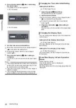
Page 39: ...lection screen appears 0 For U models 0 For E models Pусский Español Italiano Deutsch Français English Language Memo 0 The menus and messages on the screen of the LCD monitor or viewfinder are displayed in the selected language 2 Select a language using the cross shaped button JK and press the Set button R A self diagnosis screen appears 3 Ensure that the lens cover is closed and press the Set but...

Page 40: ... after Initial Setting Setting the Date Time A P155 Date Time 1 Select System B Date Time The Date Time screen appears 2 Set the date and time A Move the cursor with the cross shaped button HI and select the setting item B Change the values with the cross shaped button JK 3 Press the Set button R after setting is complete The clock is set to 0 seconds of the input date time Changing the Display St...

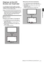
Page 41: ...ode 0 The display switches with every press of the DISPLAY button Display off B Display on B Display off 0 Press the STATUS button to switch to the status screen A P174 Status Screen 282min 1 60 F2 8 AE 0 ND1 64 12 34 56 ISO102400 00 00 00 00 5 6f t B 5600K 4030 20 10 0 Display Off Display On Display Screen VF LCD in Media Mode A P172 Display Screen in Media Mode 0 This is the screen display durin...

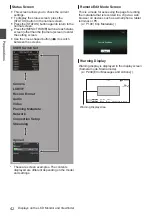
Page 42: ...etadata Network Connection Setup Streaming These are screen examples The contents displayed are different depending on the model and settings Remote Edit Mode Screen This is a mode for accessing the page for editing the metadata that is recorded in a clip via a web browser on devices such as a smartphone tablet terminal or PC A P196 Clip Metadata Exit Remote Edit Mode Warning Display Warning displ...

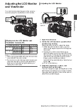
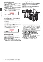
Page 43: ...CD BRIGHT 3 Tilt 90 degrees downward Tilt 180 degrees upward 1 Open the LCD cover 2 Incline the LCD monitor to a position that enables easy viewing Rotate the LCD monitor to adjust the angle 0 While the LCD monitor is open you can rotate it 180 degrees upward or 90 degrees downward 0 Rotating the LCD monitor 180 degrees upward enables you to see the screen from the lens side To display the image w...

Page 44: ... monitor 0 Adjust using LCD VF B LCD Contrast A P127 LCD Contrast 0 Increasing the value increases the contrast Setting Values 10 to 10 Default value 0 Adjusting the Viewfinder You can change the brightness and peaking of the viewfinder screen according to your usage conditions Changing the brightness of the screen will not affect the recorded images PEAKING 1 2 Caution 0 A high definition viewfin...

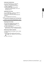
Page 45: ...sting the Contour Memo 0 To display the viewfinder screen close the LCD monitor or press and hold the DISPLAY button Adjusting the Contrast Use the VF Contrast menu to adjust the contrast of the viewfinder screen 0 Adjust using LCD VF B VF Contrast A P127 VF Contrast 0 Increasing the value increases the contrast Setting Values 10 to 10 Default value 0 Displaying in Black and White You can display ...

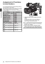
Page 46: ...R8 EXP FOCUS 9 Button USER9 Front Cross Shaped Button J USER10 Front Cross Shaped Button K USER11 Front Cross Shaped Button H USER12 Front Cross Shaped Button I USER13 USER7 USER8 ONLINE 3 OIS 2 FOCUS ASSIST 1 EXP FOCUS 9 AE LOCK 4 ZEBRA 5 MARKER 6 1 Assign functions to the buttons from the menu Configure each item to the user buttons in Camera Function B User Switch Set A P116 User Switch Set Ite...

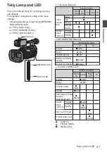
Page 47: ...Control Unit PROGRAM R PREVIEW R 0 NETWORK LED Behavior NETWORK LED Setting On Off Activating o Green Warning J Red During live streaming R Red Waiting for live streaming connection R Orange Error during live streaming R Orange 0 STATUS LED Behavior STATUS LED Setting REC Pre Rec External Return over IP Off Activating o Green Warning J Red On Pre Rec standby R Green Recording R Red Remaining space...

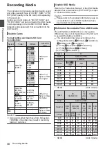
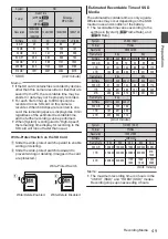
Page 48: ...hat is inserted into EXT SLOT for steps to mount the SSD media Caution 0 Please refer to the product information page on our website for a list of SSD media that have been tested for compatibility Estimated Recordable Time of SD Cards The estimated recordable time is only a guide Differences may occur depending on the SD card in use and the battery condition 0 The recordable time varies according ...

Page 49: ...tch downward to prevent writing or deleting Images in the card are protected A B Write Delete Enabled Write Delete Disabled Write Protect Switch Estimated Recordable Time of SSD Media The estimated recordable time is only a guide Differences may occur depending on the SSD media in use and condition of the battery 0 The recordable time varies according to the settings in System GFrame Rate and GBit...

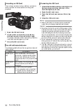
Page 50: ...t is selected Removing the SD Card 1 Check that the SD card to be removed is not being accessed status indicator of the card slot lights up in red 2 Open the SD card cover 3 Push the SD card and remove it from the slot 4 Close the SD card cover Memo 0 When both slots are inserted with usable SD cards the previously selected slot is used Caution 0 Data may be lost if you turn off the power of the c...

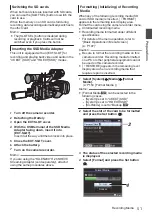
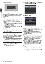
Page 51: ... above Formatting Initializing of Recording Media When any of the following recording media SD card or SSD media is inserted FORMAT appears in the remaining level display area Format the card using the camera recorder menu 0 Unformatted recording media 0 Recording media formatted under different specifications For details of the menu operation refer to Basic Operations in Menu Screen A P 107 Cauti...

Page 52: ...edia that requires repair is inserted 1 Select System B Media B Restore Media A P154 Restore Media 2 Select the recording media to be restored and press the Set button R 2 3 Restoring starts Restoring 4 Restoring is complete 0 When restoring is complete Complete appears and the camera recorder returns to the Restore Media screen 0 When no media that requires restoring is inserted the camera record...

Page 53: ...he recording media 0 An 8 character clip name is automatically generated for the recorded clip Clip Name Prefix Clip Number Example QuickTime ABCG0001 This is set to xxxG xxx denotes the last 3 digits of the serial number by default Clip Name Prefix any four alphanumeric characters The Clip Number can be reset in the menu A number in automatic ascending order is assigned in the recording order Cli...

Page 54: ...peration lock feature is turned on On 0 Remote operation from the wired remote control connected to the REMOTE terminal 0 Remote operation of the camera through access via a browser on devices such as a smartphone tablet terminal or PC Operation lock does not apply to the following buttons and switches 0 POWER ON OFF switch 0 ND FILTER switch 0 TC IN OUT switch 0 Focus Ring 0 Zoom Ring 0 Iris Ring...

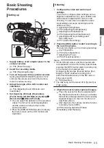
Page 55: ...recording level for audio recording 0 Adjusting the Brightness A P64 Adjusting the Brightness 0 Adjusting the White Balance A P69 Adjusting the White Balance 0 Adjusting Audio Input Settings and Recording Level A P74 Audio Recording 2 Press the REC button to start recording to the recording media The tally lamp lights up in red during recording 0 Zoom Operation A P59 Zoom Operation 0 Adjusting the...

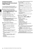
Page 56: ...576 or 480x270 suitable for web distribution 0 High Speed Records in HD resolution 1920 1080 You can select a definition for the recorded images from the following items under System 0 4K EXT SSD Performs 4K EXT recording in EXT SLOT 0 4K Records in 4K quality for both slots A and B 0 HD EXT SSD Performs HD EXT recording in EXT SLOT 0 HD Records in HD quality for both slots A and B 0 SD Records in...

Page 57: ...at G Format G Resolution G Frame Rate GBitRate ProRes 1920x1080 60p 50p 30p 25p 24p 422HQ 422 Memo 0 Rec Mode is fixed at Normal 0 Slot Mode is fixed at 0 The following functions cannot be used when HD EXT SSD is selected View Remote Live Streaming Return over IP Overlay Function Clip Cutter Trig o When System is set to HD or HD Web the options for slot A are Record Format W Format W Resolution W ...

Page 58: ... media runs out faster than usual Example For 120 60p as the recording speed is twice as fast as usual the remaining space on the media is reduced by approximately double the speed o When System is set to SD Record Format W Format W Resolution W Frame Rate W Bit Rate QuickTime H 264 720x480 60i U model 8M HQ 720x576 50i E model Memo 0 The following function cannot be used when SD is selected Overl...

Page 59: ...om lever at the handle to zoom Memo 0 When the FIX VAR OFF zoom speed switch is set to OFF the zoom lever at the handle section cannot be used Using Zoom Ring at the Lens Section You can adjust the preferred angle of view by turning the zoom ring Saving Recalling Current Zoom Position Preset Zoom This allows you to register up to three zoom positions 1 Assign the Preset Zoom1 Preset Zoom2 or Prese...

Page 60: ...y Push Auto Focus 0 The camera recorder will shift to Auto Focus mode temporarily and automatically adjusts focus when the PUSH AUTO button is pressed during shooting in Manual Focus mode 0 Release the PUSH AUTO button to return to Manual Focus mode Memo 0 Face detection does not work during Push Auto Focus Locking the Focus While in the Auto Focus mode pressing the PUSH LOCK button locks the focu...

Page 61: ... 1 button is pressed during shooting the focused area is displayed in color This enables easy and accurate focusing 0 Select the color blue red or green in the menu Memo 0 When LCD VF B Shooting Assist B Focus Assist B Type is set to ACCU Focus the depth of field becomes shallower to enable easier focusing A P128 Focus Assist 0 The ACCU Focus function switches automatically to Off after about 10 s...

Page 62: ...et the operation when the button is pressed go to Camera Function B User Switch Set B Expanded Focus A P118 Expanded Focus 0 Pressing and holding the Set button R resets the position of magnification 0 This function can be used together with the Focus Assist function 0 Magnifying an image does not alter the size of the recorded image 0 The cross shaped button cannot be used as user button while th...

Page 63: ...ightnessAdjustment AE Mode A P65 Auto Iris Automatic Adjustment Mode A P66 Automatic Gain Mode Automatic Gain Adjustment A P67 Automatic Shutter Mode Automatic Shutter Adjustment Selecting Specific Person from Several Persons 1 Hold down the user button that is assigned with Face Detection 0 The camera recorder will enter face selection mode and the face detection icon q will blink 0 An orange fra...

Page 64: ...LL AUTO switch to ON to enter the Full Auto mode also activates the automatic brightness adjustment AE mode In this case white balance is also switched forcibly to auto mode 0 The convergence speed of the automatic adjustment for automatic brightness adjustment AE can be set in the menu A P111 AE Speed 0 If one or more of the items Gain Iris and Shutter have been set to Auto mode the value of the ...

Page 65: ...the IRIS button to set to the Manual Iris mode The lens aperture value F number is displayed 1 60 F2 8 AE 0 ND1 64 12 34 56 ISO102400 00 00 00 00 5 6f t B 5600K 3 Turn the iris ring on the lens to adjust the iris manually The open F number of the aperture varies according to the zoom position Wide W end F2 8 Tele T end F4 5 F number Description Decrease The subject appears brighter The focused ran...

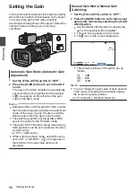
Page 66: ...n of the GAIN L M H switch is disabled in the Full Auto mode 0 The upper limit of the gain setting value during AGC operation can be set in Camera Function B AGC Limit A P111 AGC Limit 0 While in the Auto Gain mode and AE Lock is set to AE or AE FAW a icon appears on the left side of the gain value during lock operation Manual Gain Mode Manual Gain Switching 1 Set the FULL AUTO switch to OFF 2 Pre...

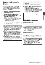
Page 67: ...etbutton R are disabled 0 While in the Automatic Shutter mode and AE FAW Lock is set to AE or AE FAW a icon appears on the left side of the shutter speed during lock operation Manual Shutter Mode Manual Shutter Switching 1 Set the FULL AUTO switch to OFF 2 Press the SHUTTER button to set to the Manual Shutter mode 0 The a icon on the screen disappears 0 Use the Set button R to switch between the s...

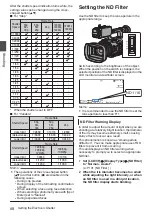
Page 68: ...a photometry area with Spot Meter set to Manual 0 During expanded focus Setting the ND Filter Use the ND filter to keep the lens aperture in the appropriate range Switch according to the brightness of the object When the position on the switch is changed the selected position of the ND filter is displayed on the LCD monitor and viewfinder screen 1 60 F2 8 AE 0 ND1 16 12 34 56 ISO102400 00 00 00 00...

Page 69: ...t takes about 15 seconds for the colors to stabilize Memo 0 Setting the FULL AUTO switch to ON to enter the Full Auto mode also activates the Automatic White Balance mode In this case the Iris Gain and Shutter also enter into Auto mode forcibly 0 When Camera Function B User Switch Set B AE Lock is set to AE FAW or FAW the white balance when the user button that is assigned with AE Lock is pressed ...

Page 70: ...Alternative Temp Values You can change both the color temperature settings in the Preset mode in the menu 1 Open the Preset Temp or Alternative Temp menu 0 Select Camera Process B White Balance B Preset Temp and Alternative Temp and press the Set button R 0 The Color Temperature setting screen appears ColorTemperature Detailed Selection Screen Color Temperature Selection Screen 2 Select the color ...

Page 71: ...lue will be saved in Memory A or Memory B 1 Prepare the camera recorder A Set the POWER ON OFF switch to ON B Set the FULL AUTO switch to OFF C Press the IRIS button to set to the Auto mode 2 Set the ND FILTER switch according to the lighting A P68 Setting the ND Filter 3 Set the WHT BAL B A PRESET selection switch to A or B 4 Locate a place with similar lighting conditions as the object to be sho...

Page 72: ...he white balance saved in Memory A or Memory B 1 Select Camera Process B White Balance B AWB Paint and press the Set button R The White Paint Adjustment screen appears 1 AWB Paint White Balance 2 Adjust the R and B values Use the cross shaped button JK to adjust R value and HI to adjust B value B R 3 Press the Set button R Returns to the White Balance screen B Value R Value AWB Paint White Balance...

Page 73: ... feature when image stabilizer feature is OFF The image stabilizer feature switches between ON and OFF with every press of the OIS 2 button 0 OFF Use this setting when the camera recorder is secured such as when using a tripod 0 ON Reduces blurring of images due to camera shake Memo 0 Select Camera Function B OIS B Level to set the correction level A P111 Level 0 Correction by this feature may not...

Page 74: ...et B Audio Set B Int Mic Gain AUX Gain A P135 Int Mic Gain A P135 AUX Gain Setting Input Channel to INPUT1 INPUT2 Select the audio to input to INPUT1 and INPUT2 terminals with the INPUT1 INPUT2 mode switch Setting Description LINE Use this setting when connecting to an audio device or other equipment The reference input level is 4 dBu MIC Use this setting when connecting to a dynamic microphone MI...

Page 75: ...n the built in microphone and the AUX input terminal are used the recording levels of CH1 and CH2 are interlocked This is also effective when the CH1 AUTO MANUAL selection switch is set to CH2 Memo 0 Select Limiter AGC Response AGC Mode or Int Mic Separation in the menu to set the recording audio 0 If Limiter is set to other than Off the limiter operates according to the value set A P135 Limiter 0...

Page 76: ...to BOTH 2 Set A V Set B Audio Set B Monitor to Stereo A P136 Monitor Memo 0 You can set the volume of the warning tone in A V Set B Audio Set B Alarm Level Off Low Middle High A P137 Alarm Level Time Code and User s Bit Time code and user s bit data are recorded with the video in this camera recorder The time code and user s bit are displayed on the viewfinder and LCD monitor during playback or re...

Page 77: ...laced the last time code recorded on the card is read and recorded on a new card so that the time code continues in running order A P78 Setting Time Code Memo 0 When System B Record Set B Rec Mode is set to Interval Rec or Frame Rec and TC Generator is set to Free Run Free Run Ext or Free Run NTP Rec Run is activated 0 When System B Record Set B Record Format B System is set to High Speed and TC G...

Page 78: ...es of 10 However in the case of 60p the 00 01 02 and 03 frame are dropped 0 The non drop frame mode Non Drop does not drop frames and ignores the discrepancy with the actual time Setting Time Code 1 Select TC UB B TC Preset and press the Set button R A P125 TC Preset The TC Preset screen appears 1 TC Preset 00 00 00 00 TC UB Memo 0 When TC UB B TC Generator is set to Regen the parameter is display...

Page 79: ...and the screen returns to the normal screen 0 To cancel the setting press the CANCEL button Caution 0 When the camera recorder is switched to Media mode during editing editing will be canceled and the screen will close 0 When editing the time code operation of the buttons that are set in Camera Function B User Switch Set is disabled OIS 2 functions as the number reset button A P116 User Switch Set...

Page 80: ...ode 1 TC UB UB Mode Preset Time Preset Date Memo 0 When TC UB B TC Generator is set to Regen the parameter is displayed as Regen and cannot be selected A P125 TC Generator 2 Select TC UB B Preset and press the Set button R The Preset setting screen appears 3 Use the cross shaped button HI to place the cursor at the item to set then use the cross shaped button JK to change the values Numbers betwee...

Page 81: ...s 2 Set TC UB B TC Generator as follows 0 Slave device Select Free Run Ext 0 Master device Select Free Run 3 Set LCD monitor or viewfinder to Display screen 4 Set the master device and run the time code 0 When the built in time code generator is synchronized with the external time code data input the Z icon on Display screen lights up 0 When time code is not synchronized or time code input is not ...

Page 82: ... 5 10 to 95 98 100 Over Bottom Lower luminance limit for displaying Zebra 0 5 to 95 98 100 Memo 0 The timing to detect the zebra pattern display can be configured only when J Log1 or HLG is selected in Color Space and Cam or Cam Return is selected in Convert to ITU709 A P119 Color Space A P127 Convert to ITU709 A P128 Detect 3 Display the zebra pattern Press the ZEBRA 5 button to display the zebra...

Page 83: ...ghtness range of 0 to 458 is displayed 0 When Color Space is set to J Log1 the dynamic range of the camera recorder is max 800 and a brightness range of 0 to 800 is displayed Memo 0 Spot meter may not be consistent with the zebra display range 1 Select one of the following from Camera Function B User Switch Set B Spot Meter A P117 Spot Meter Item Settings Color of Frame Indicating the Position Max...

Page 84: ... brightness levels are displayed D By pressing the button the cursors and brightness indication disappear When Manual is selected A The brightness of the cursor position is displayed when the button is pressed Cursor Green Brightness Indication B By pressing the button the cursors and brightness indication disappear C Hold down the button in the state in A or B the cursor blinks in green Move the ...

Page 85: ...UTC and positioning information can be obtained and recorded GPS reception in progress signal strength medium Receiving GPS signal UTC and positioning information can be obtained and recorded Display Reception Status Positioning Status GPS reception in progress signal strength strong Receiving strong GPS signal UTC and positioning information can be obtained and recorded No display GPS function is...

Page 86: ...0 During Clip Review only the CANCEL and REC buttons are enabled Press the CANCEL button to cancel clip review and return to STBY recording standby mode Press the REC button to cancel clip review and enter recording mode It will take some time to start recording after the button is pressed 0 When the last clip is less than 5 seconds the whole clip is played back 0 Only video clips in the currently...

Page 87: ...Two Different Definitions By setting System to HD Web you can record simultaneously at two different definitions 0 When HD Web is selected Records a high definition HD file to slot A and a web file to slot B at the same time Web files can be used as a proxy file for the HD file Memo 0 If a recordable SD card is inserted into only one of the slots files will only be recorded to that slot 0 The Rec ...

Page 88: ...C button again 0 Recording to both slots stops and both the card slot marks turn white 0 The same clips are recorded to both cards 100min 50min 282min 1 60 F2 8 AE 0 ND1 64 12 34 56 ISO102400 00 00 00 00 5 6f t B 5600K 4030 20 10 0 White Memo 0 During recording in the Dual Rec mode both the card slot marks light up in red 0 During recording in the Dual Rec mode to two cards with a different amount...

Page 89: ...by the recovery function may fail 0 If an error occurs on one of the cards while recording is in progress in the Dual Rec mode recording of the erroneous card stops while that of the other card continues 0 Operations on clips recorded in the Dual Rec mode such as clip deletion in the Media mode or appending of OK marks can only be performed on the card in the selected slot Backup Rec 0 Backup Rec ...

Page 90: ...5 6f t B 5600K 4030 20 10 0 50min 100min Red selected 3 Start normal recording normal recording into slot A 0 Press any of the REC buttons 0 Recording into the media in slot A starts The characters RREC appear in red 0 The card icon of slot A turns red unselected state and the status indicator of slot A blinks in red 100min 50min 282min 1 60 F2 8 AE 0 ND1 64 12 34 56 ISO102400 00 00 00 00 5 6f t B...

Page 91: ...nce they are recorded seamlessly 0 Clip Cutter Trig cannot be performed during backup recording A P96 Splitting the Clips Freely Clip Cutter Trig 0 When Slot Mode is configured to Backup Y or Backup G Rec Mode cannot be configured to a setting other than Normal A P160 Rec Mode Special Recording Besides the normal recording mode four special recording methods are available in this camera recorder T...

Page 92: ...hing from Media mode to Camera mode 0 Immediately after setting Rec Mode 0 Immediately after the end of Clip Review 0 Immediately after changing file format 0 Immediately after changing video format Clip Continuous Rec 0 In normal recording when the recording stops the image audio and accompanying data from the start till the end of the recording are recorded as one clip on the SD card 0 This mode...

Page 93: ...C button again 0 The display changes STBYL B RRECL and the card slot status indicator lights up in red 0 A new clip is generated from here Memo 0 The following operations cannot be performed while recording is paused STBYL yellow text 0 Clip Review operation A P86 Viewing Recorded Videos Immediately Clip Review 0 Switching SD card slots 0 Switching operation mode A P24 Operation Modes 0 Files are ...

Page 94: ...e to Frame Rec 0 Set System B Record Set B Rec Mode to Frame Rec A P160 Rec Mode 0 The display changes STBY B STBYM 2 Set the number of frames to record in Rec Frames 0 To configure the setting go to System B Record Set B Rec Mode B Rec Frames A P160 Rec Frames 3 Start recording 0 Press the REC button to record only the number of frames specified in Rec Frames and pause 0 The display changes STBYM...

Page 95: ...c A P160 Rec Mode 0 The display changes STBY B STBYN 2 Set the number of frames to record in Rec Frames To configure the setting go to System B Record Set B Rec Mode B Rec Frames A P160 Rec Frames 3 Set the time interval to start recording in Interval Rec To configure the setting go to System B Record Set B Rec Mode B Rec Interval A P160 Rec Interval 4 Start recording 0 Press the REC button to rec...

Page 96: ...on cannot be used Configuring Infrared Recording This camera recorder comes with a infrared recording mode that is suitable for night recording Using infrared illumination allows images to be captured naturally in a pitch dark environment It is recommended for observation of animals without alerting them or for natural facial expressions without firing glaring flash light at the subject 1 Set the ...

Page 97: ...he clip selected by the cursor 0 If an OK mark has been appended it will be deleted Otherwise an OK mark will be appended F OIS 2 Button 0 Switches the selection status of the clip selected by the cursor 0 Clips being selected are displayed with check mark G ONLINE 3 Button Enters the action selection screen H DISPLAY Button Switches between the Standard Screen and Detailed Screen I STATUS Button ...

Page 98: ...nor displayed in thumbnail with the current video format settings It cannot be played back even if you press the Set Play button Memo 0 This is dependent on the System Format Resolution Frame Rate and Bit Rate settings in the System B Record Set B Record Format menu A P156 System E Clip Name The file name clip number of the selected clip is displayed F Operation Guide 0 Displays a guide for the cu...

Page 99: ... button is pressed The following operations can be performed Item Description Select All Clips Selects all clips Select OK Marked Selects all clips appended with OK mark Select Range Specifies the range when selecting multiple clips A P104 Selecting Multiple Clips Randomly Deselect All Clears all clip selections Add OK Mark Appends an OK mark 0 This Clip Appends an OK mark to the clip pointed by t...

Page 100: ...WHT BAL GAIN CANCEL MENU THUMB AE LEVEL ONLINE 3 OIS 2 FOCUS ASSIST 1 TIME CODE C B A A Set Button R 0 Plays back pauses the clip pointed by the cursor 0 You can press the cross shaped button HI to perform frame by frame forward playback during pause mode B Cross shaped Button JKH I 0 J K Button Skips in the reverse or forward direction 0 H I Button 0 During Playback Fast forwards in the reverse o...

Page 101: ... during shooting switches the display information between camera information display GPS display and turning off the display 0 The GPS display displays information on the recording location of the video being played back only when GPS information has been recorded 0 Camera information display displays only information of Gain Iris Shutter and White Balance that have been recorded 5600K 1 100 F1 6 ...

Page 102: ...nd press the Set button R A screen to confirm deletion appears 3 All Clips Selected Clips This Clip 4 Select Delete using the cross shaped button JK and press the Set button R Deleting starts 4 Stop Deleting Cancel Delete Delete This Clip Selecting and Deleting Multiple Clips To select and delete multiple clips refer to Selecting and Performing Operations on Multiple Clips A P 104 Deleting All Cli...

Page 103: ...mark will be appended 0 If the clip is appended with an OK mark the OK mark will be deleted OK Mark During Playback or Pause Screen 1 Press FOCUS ASSIST 1 button during clip playback 0 If the clip does not have an OK mark an OK mark will be appended 0 If the clip is appended with an OK mark the OK mark will be deleted OK Mark Memo 0 The clip pauses when an OK mark is appended or deleted during pla...

Page 104: ...n check mark appears on the clip 1 2 Repeat Step 1 to select multiple clips 0 Multiple clips can be selected 0 Press the ONLINE 3 button while the multiple clips are selected 0 Appends OK mark together Add OK Mark B Selected Clips 0 Deletes OK mark together Delete OK Mark B Selected Clips 0 Uploading selected clips to the FTP server together FTP Upload B Selected Clips 0 Deletes selected clips tog...

Page 105: ... the range 0 The check marks change from magenta to green 0 Pressing the ONLINE 3 button while the multiple clips are selected displays the action selection screen The following operations can be performed 0 Appends OK mark together Add OK Mark B Selected Clips 0 Deletes OK mark together Delete OK Mark B Selected Clips 0 UploadingselectedclipstotheFTPserver together FTP Upload B Selected Clips 0 D...

Page 106: ...erformed in this case 0 When System B Record Set B Record Format B WFrame Rate is set to 70M XHQ Duration appears in yellow if the duration is 6 minutes or longer Trimming cannot be performed in this case 0 When System B Record Set B Record Format B System is configured to 4K EXT SSD or 4K Duration appears in yellow if it is 3 minutes or longer Trimming cannot be performed in this case 0 When Syst...

Page 107: ...RKER 6 SHUTTER WHT BAL GAIN CANCEL MENU THUMB AE LEVEL ONLINE 3 OIS 2 FOCUS ASSIST 1 TIME CODE STATUS DISPLAY PEAKING C 8V CH2 C F B E D A G A FOCUS ASSIST 1 Button Adds the selected menu or submenu item to the Favorites Menu B OIS 2 Button Resets settings in the TC Preset or UB Preset setting screen C MENU THUMB Button 0 Displays the menu screen The Main Menu screen is displayed by default 0 Duri...

Page 108: ...Remaining Battery Power A P37 Power Status Display Memo 0 If the supplied battery or equivalent battery sold separately is not used the battery mark which indicates the battery level may not appear I Menu Title Title of the currently displayed menu Changing Setting Values Cancel Set Off SEC Shutter 24hour Time Style YMD Date Style Date Time Battery Audio Meter Display Settings On D F A C B E A Men...

Page 109: ... the arrow keys H C Character Keys Use the cross shaped button JKHI to move the key cursor D to the character you want to enter D Key Cursor Indicates the currently selected character or item Use the cross shaped button JKHI to move the cursor E Confirmation Buttons 0 Select Set Store and press the Set button R to confirm the title 0 Select Cancel and press the Set button R on the side control pan...

Page 110: ...709 A P 127 LCD RGB Gain A P 128 VF RGB Gain A P 128 A V Set A P 132 Video Set A P 132 Audio Set A P 135 Network A P 138 Connection Setup A P 138 Live Streaming A P 138 Return over IP A P 138 Web A P 138 Metadata Server A P 138 Upload Settings A P 138 Import Metadata A P 139 Zero Config A P 139 Reset Network A P 139 Overlay Settings A L A P 151 Overlay Function A P 151 Layout A P 151 Import User L...

Page 111: ...ur occurs when switching between On and Off Shutter For specifying shutter related settings Configure the value to Step fixed value or Variable when operating the shutter with the cross shaped button J K on the side of the camera recorder unit 0 Variable Sets to variable scan Use this setting when shooting a PC monitor 0 Step Sets to step shutter which switches the shutter speed by a fixed value S...

Page 112: ...AIN M GAIN H For setting the gain value of each position on the GAIN selection switch The setting is fixed at AGC in the Full Auto mode In addition the sensitivity setting in Lolux is used A P117 Lolux 0 When LCD VF B Display Type B Gain is set to dB Setting Values 24 dB 21 dB 18 dB 15 dB 12 dB 9 dB 6 dB 3 dB 0 dB 3 dB 6 dB Default values for GAIN L 0dB GAIN M 6dB GAIN H 12dB 0 When LCD VF B Displ...

Page 113: ...o ON Setting Values RKeylock Except Rec Keylock All Menu Access For specifying settings on the behavior when accessing the menu using the MENU THUMB button Setting Values Press and Hold ROne Press Camera Angle Tagging L For specifying tagging settings for the camera angle Setting Values SB RSL EZ SL2 EZ2 TV Zoom Function Settings Dynamic Zoom For setting whether to enable the dynamic zoom function...

Page 114: ...s before the operation stops Setting Values 1 to 5 ROff REMOTE Zoom Ease For specifying whether to zoom in or zoom out slowly when zoom operation starts or during zooming using a wired remote control 0 Off Disables zoom ease 0 1 Enables zoom ease 0 2 Enables zoom ease Maximum zoom speed is about half of that in 1 0 SW Set Switches between Off 1 and 2 using the zoom speed selection switch Switch po...

Page 115: ...0 Wide Extends the AF area sideways 0 Normal Performs AF at the area near the center of the image Setting Values Multi Wide RNormal MF Assist For specifying the behavior when the focus ring is turned during MF 0 On Turning the focus ring during MF activates AF for a short interval after the operation after which the camera recorder returns to the MF mode However it does not function while in the e...

Page 116: ...ition for some time even if the face on the screen is lost Setting Values Long RNormal Short User Switch Set Item USER1 to USER9 USER10 USER11 USER12 USER13 Assigning one of the functions in the following menu to the FOCUS ASSIST 1 OIS 2 ONLINE 3 AE LOCK 4 ZEBRA 5 MARKER 6 USER7 USER8 or EXP FOCUS 9 button or the 10 11 12 or 13 front cross shaped button enables operation of the said preconfigured ...

Page 117: ...ing to the setting of LCD VF B Convert to ITU709 White Level AE Lock For configuring the behavior when operating the user button that is assigned with the AE Lock function 0 FAW Use this to fix the FAW Full time Auto White Balance function to the value when the user button assigned with AE Lock is pressed 0 AE Use this to fix the Auto function of Gain Iris or Shutter to the value when the user but...

Page 118: ...anded Focus function is enabled during the interval while the user button assigned with Expanded Focus is pressed 0 Toggle Pressing the user button assigned with Expanded Focus each time switches the Expanded Focus function to on or off Setting Values Limited Time Momentary RToggle Memo 0 When one of the J 10 K 11 H 12 I 13 buttons is assigned with Expanded Focus and Toggle is selected press the C...

Page 119: ...G is selected 9 Colorimetry For configuring the standard for converting R G B signals to Y Cb Cr signals when Color Space is configured to HLG or ITU2020 0 ITU2020 Records and outputs ITU2020 RGB signals using the Y Cb Cr signal conversion coefficient 0 ITU709 Records and outputs ITU709 RGB signals using the Y Cb Cr signal conversion coefficient Setting Values RITU2020 ITU709 Memo 0 This item is a...

Page 120: ...Detail For adjusting the contour detail enhancement level Increasing the value increases the sharpness of the contour Setting Values 10 to 10 Off Default Value 6 for J Log1 and HLG of Color Space 0 for all other settings Memo 0 The setting values of this item and Adjust are stored separately when Color Space is set to HLG or J Log1 0 This item cannot be configured when Infrared is set to On 9 Freq...

Page 121: ...evel Compression amount increases when a larger value is specified Setting Values 5 to 1 R 3 Memo 0 This item is displayed only when Black Toe is set to Compress Otherwise this item appears as and cannot be selected 0 This item cannot be configured when Color Space is set to J Log1 or HLG 0 This item cannot be configured when Infrared is set to On Knee For specifying the Knee operation which compr...

Page 122: ...0 This item cannot be configured when Color Space is set to J Log1 or HLG and when Gamma is set to Cinema 2 0 This item cannot be configured when Infrared is set to On White Clip For setting the point to apply white clip for video signals with a high luminance level 0 109 Applies white clip at the point where the luminance level is 109 0 103 Applies white clip at the point where the luminance leve...

Page 123: ...Color Space is set to J Log1 0 This item cannot be selected when Color Matrix is set to Off 0 This item cannot be configured when Infrared is set to On Color Gain For adjusting the video signal color level Increasing the value deepens the color Setting Values 15 to 50 Off R0 Memo 0 Images are displayed in black and white when this is set to Off 0 This item cannot be configured when Color Space is ...

Page 124: ... Setting Values 32 to 32 R 0 AWB Paint For adjusting the R red B blue component in the AWB Auto White Balance mode For details refer to Adjusting the White Balance A P 69 0 Increase the number Strengthens the red blue 0 Decrease the number Weakens the red blue Setting Values 32 to 32 R 0 Memo 0 This item is selectable when the WHT BAL switch is set to A or B When PRESET is set this item appears as...

Page 125: ...ode operates in the run mode during recording When the SD card is replaced the last time code recorded on the card is read and recorded on a new card so that the time code continues in running order Setting Values Free Run NTP Free Run GPS L Free Run Ext Free Run RRec Run Regen Memo 0 When Rec Mode is configured to Interval Rec or Frame Rec only Rec Run and Regen are selectable 0 When System is co...

Page 126: ...abled Drop Frame For setting the framing mode of the time code generator 0 Non Drop Internal time code generator works in the non drop frame mode Use this setting when placing emphasis on the number of frames 0 Drop Internal time code generator works in the drop frame mode Use this setting when placing emphasis on the recording time Setting Values Non Drop RDrop Memo 0 This item can be set only wh...

Page 127: ...e viewfinder screen Increasing the value increases the contrast Setting Values 10 to 1 R0 1 to 10 LCD Contrast For setting the difference in luminance between the darkest and brightness areas in the LCD monitor Increasing the value increases the contrast Setting Values 10 to 1 R0 1 to 10 LCD Backlight For setting the brightness of the LCD monitor backlight Increasing the value increases the bright...

Page 128: ...VF RGB Gain to the default settings Shooting Assist Item Focus Assist For setting whether to add color to the contour of the focused image upon switching the image to black and white Setting Values On ROff 9 Type For configuring the behavior when operating the user button that is assigned with the Focus Assist function A P61 Focus Assist Function 0 ACCU Focus Enables the Focus Assist and ACCU Focu...

Page 129: ... Color Space is set to J Log1 a green line appears which corresponds to the 0F stop 18 portion of the subject with 18 reflectance 9 Histogram Bottom For selecting the minimum brightness limit for changing the histogram display color Setting Values 0 to 105 in 5 increments R 20 0 When Color Space is set to J Log1 Setting Values 6F stop 5F stop 4F stop R 3F stop 2 2F stop 1F stop 0F stop 18 F stop F...

Page 130: ... ratio selected in Aspect Ratio Setting Values ROn Off Display Type Item This menu is used to set the displays on the LCD monitor and viewfinder screen Battery For setting the display of the remaining battery power on the LCD monitor and viewfinder screen 0 Time Displays the remaining battery power in minutes min 0 Capacity Displays the remaining battery power in percentage 0 Voltage Displays the ...

Page 131: ...shutter display setting is fixed at SEC and cannot be selected A P158 WFrame Rate GFrame Rate Gain For setting the gain display to be displayed on the LCD monitor and viewfinder screen 0 ISO Displays the gain as ISO sensitivity 0 dB Displays the gain in dB decibel Setting Values ISO RdB Memo 0 This item cannot be configured when Color Space is set to HLG Display On Off Item For setting whether to ...

Page 132: ...utput is selected the setting is fixed at Off 0 This item is fixed at Off when the HDMI SDI OUT item is displayed and a setting other than SDI is selected 9 Character For configuring whether to show the display and menu on the SDI OUT terminal Setting Values On ROff 9 Resolution For selecting the resolution of video output from the SDI OUT terminal according to the monitor to be connected Setting ...

Page 133: ...This item can be configured when SDI OUT is configured to On and Rec Mode is configured to Normal Pre Rec or Clip Continuous 0 Set to Off if connecting to a device that does not support record trigger HDMI OUT For configuring video output from the HDMI terminal Setting Values On ROff Memo 0 Monitor and menu displays are not output from the HDMI terminal 0 This item is fixed at Off when the HDMI SD...

Page 134: ...c Trigger For configuring whether to superimpose trigger signals on the HDMI out terminal in tandem with the REC button If On is specified it is possible to record on a device equipped with HDMI record trigger in tandem with the operation of the REC button When a compatible device is connected recording stop control signals are output in tandem with the operation of the REC button The HDMI record ...

Page 135: ...ions at 6dBFS when AUTO is set Setting Values 9dBFS R 6dBFS Off AGC Response 9 Attack Time Sets the time to activate the limiter Setting Values Fast RMiddle Slow 9 Decay Time Sets the time to deactivate the limiter operation Setting Values Fast RMiddle Slow AGC Mode For setting whether to link the limiter operation of CH1 and CH2 Select Link to link or Separate to separate Setting Values Link RSep...

Page 136: ... reduce wind noise from the microphone Setting Values On ROff Equalizer You can correct the characteristic and enhance the sound of the connected microphone using this equalizer setting For setting the audio frequency from a 5 band equalizer 0 Frequency 100Hz 330Hz 1kHz 3 3kHz 10kHz 0 Variable level 6dB 1dB step Memo 0 Audio will be recorded in the characteristic set in the equalizer 0 Set all ban...

Page 137: ...ng Values RAuto IFB RET Only Off Memo 0 To enable different settings for CH1 and CH2 of IFB RET Monitor set Monitor to Stereo Alarm Level For selecting whether to turn on the warning tone as well as setting the volume The warning tone is output from the monitor speaker or x terminal Setting Values RHigh Middle Low Off Audio On FULL AUTO For setting whether to enable Auto for audio when the FULL AU...

Page 138: ...t to 24p Return over IP For configuring settings related to Return over IP This function allows video and audio to be received via the network A P145 Return over IP Item Memo 0 Users cannot access this menu in the following cases 0 Recording 0 When Record Format B System is set to a setting other than HD or SD 0 When Record Format B Frame Rate is set to 24p 0 When Overlay Settings B Overlay Functi...

Page 139: ...twork However Not Synchronized is displayed if the unit is not connected to a network when the power is turned on Zero Config For allowing this camera recorder to be detected automatically by external devices such as switchers connected to the same LAN Connection can be established via one link from the menu of the external device Memo 0 The Zero Config function is not equipped with the function t...

Page 140: ...rectly A P187 Cellular adapter connection USB Cellular Live Streaming Item Live Streaming Starts live distribution when On is selected Setting Values On ROff Memo 0 On cannot be selected if streaming is not possible with the selected resolution frame rate and bitrate combination 0 On cannot be selected if connection of the selected network is not established 0 On cannot be selected when FTP is run...

Page 141: ...ormed before using the SRT protocol Doing so will make the Zixi protocol unusable To enable the use of the Zixi protocol again perform Zixi protocol update 0 The following items that can be set vary depending on the setting of this item o Connection Mode For configuring the SRT connection mode Setting Values RCaller Listener Rendezvous Memo 0 This item is selectable only when Type is set to SRT o ...

Page 142: ... For setting the latency mode Setting Values High Medium RLow Min Memo 0 This item is selectable only when Type is set to ZIXI o PCR Mode For configuring the low latency mode Setting Values Fast RStandard Memo 0 Available when Type is set to MPEG2 TS UDP MPEG2 TS RTP ZIXI or SRT 0 Configuring to Fast minimizes the lag but the video image may be disrupted depending on the shooting and network condi...

Page 143: ...or selecting Facebook Live Timeline or a page name to upload a post o Title For configuring the YouTube Live title o Schedule For configuring the date time to start YouTube Live streaming to ON OFF Select On to enable Settings Setting Values On Off o Settings For configuring the date time to start YouTube Live streaming o Privacy For configuring the privacy settings of Facebook Live Setting Values...

Page 144: ...gs in Live Streaming Set B Resolution and Bit Rate For details on the settings please refer to Distributable RecordFormat and LiveStreaming Set Combinations A P 216 Memo 0 The setting cannot be changed during live streaming when Live Streaming set to On 0 Depending on the type of network adapter used and the connection images and audio sound during live streaming may be choppy Interlace Format For...

Page 145: ...is set to On 0 When Return over IP B Function is configured to Disable this item cannot be changed A 9 Return Server For configuring the source server for sending out Return over IP audio video Memo 0 The setting cannot be changed while Return over IP is operating when Return over IP is set to On 9 Server1 Server2 Server3 Server4 The name that is set in Alias is displayed individually o Alias For ...

Page 146: ... even numbers from 2 to 65530 can be specified for the port number o Port Enter a SRT port number using an integer between 1 and 65535 The default value is 6510 Memo 0 This item is selectable only when Type is set to SRT o Stream ID For configuring the stream ID registered on the video audio transmission source There is no default value blank Enter not more than 63 characters Memo 0 This item is a...

Page 147: ... When Record Format B Frame Rate is set to 50p 50i or 25p Setting Values R50p 25p Memo 0 This item is available for setting when Type is set to RTSP RTP ZIXI or SRT Web Item Web Access To access via a web browser set to On Setting Values ROn Off Camera Name For setting the name to be displayed on the web browser Enter not more than 8 characters using the software keyboard Default value HC550 A HC5...

Page 148: ... value varies with the protocol setting FTP 21 SFTP 22 FTPS 990 FTPES 21 o File Path Enter the path name for the metadata file pub meta xml home user meta2 xml etc 0 Enter not more than 127 characters o Username Enter the user name for connecting to the FTP server Enter not more than 31 characters o Password Enter the password for connecting to the FTP server Enter not more than 31 characters o PA...

Page 149: ...ra The name set in this item will appear on the FTP Upload action screen of the thumbnail display Enter not more than 31 characters o Protocol For setting the protocol of the FTP server to be connected 0 FTP Protocol that does not encrypt the incoming and outgoing data 0 SFTP Protocol that encrypts incoming and outgoing data using SSH 0 FTPS Protocol that encrypts incoming and outgoing data using ...

Page 150: ...re than 31 characters o Stream ID A For configuring the stream ID that is registered at the distribution destination The default value varies with the product model Enter not more than 63 characters Memo 0 This item is selectable only when Type is set to ZIXI o Password Enter the password for connecting to the FTP server Enter not more than 31 characters Enter not more than 127 characters for ZIXI...

Page 151: ...lecting System B Reset All Delete the file from the camera recorder Type By selecting Type overlay images can be displayed The selectable types of scoreboards vary with the Layout settings L Setting Values Broadcast RNone A Setting Values Broadcast Basketball Baseball Football Type 2 Type 1 RNone L Memo 0 Selecting Layout or Type of the scoreboard overlay imported using Import User Layout displays...

Page 152: ...ys watermark 0 Off Does not display watermark Setting Values On ROff Memo 0 It can be displayed when the SDP file for which Watermark is preconfigured is selected in Layout 9 Position The display position of the watermark can be changed by using the cross shaped button Full Screen Graphic Images can be displayed across the whole screen 9 Status For displaying the number of images saved in this cam...

Page 153: ...portzcast A license name that is currently in use by another camera cannot be used 9 BOT Number Enter the BOT number provided by Sportzcast 9 Channel Enter the channel provided by Sportzcast Score Input Source For selecting whether to acquire the next score information from the server or to manually input the score from the web browser screen when Sportzcast is set to Connect This option comes in ...

Page 154: ...e menu settings as well as the performance results of shutter speed and AWB It is useful to save settings according to different shooting conditions 9 Load File Loads the settings A P181 Loading a Setup File 9 Store File Saves the settings A P180 Saving Setup Files 9 Delete File Deletes the settings A P181 Deleting Setup Files Tally Lamp For setting whether to light up the tally lamp during record...

Page 155: ...ol U model Setting Values REnglish Français Deutsch Italiano Español Pусский Türkçe E model Reset All Resets all menu settings Memo 0 Date Time and Time Zone cannot be reset A P155 Date Time A P156 Time Zone 0 This item is not selectable when recording in Camera mode during Clip Review during live streaming and in Media mode Date Time For setting the year month day hour and minute Memo 0 The displ...

Page 156: ... Source License Displays the license for the open source software used by this camera recorder Record Set Item Record Format After setting of all items in the Record Format menu is complete select Set at the bottom of the screen to apply the new settings on the camera recorder and switch the recording format A Please Wait message appears during switching 9 System For selecting a system definition ...

Page 157: ...ts Video Interoperability Group Inc 9 WResolution GResolution For selecting the size of the still image to be recorded to the recording media in slot A or EXT SLOT Horizontal x vertical Theavailableoptionsvaryaccordingtothesettings of System and WFormat 0 When System is set to 4K EXT SSD or 4K Fixed at 3840x2160 0 When System is set to HD EXT SSD Fixed at 1980x1080 0 When System is set to HD and W...

Page 158: ... slot A or EXT SLOT Theavailableoptionsvaryaccordingtothesettings for System WResolution GResolution and WFormat GFormat 0 When System is set to 4K EXT SSD Setting Values 422HQ 422 422LT 0 When System is set to 4K Setting Values 150M 150M 70M 0 When System is set to HD EXT SSD Setting Values 422HQ 422 0 When System is set to HD WFormat is set to QuickTime MPEG2 or MXF MPEG2 A and WResolution is se...

Page 159: ...ng as WResolution 9 Y Frame Rate The frame rate of the image to be recorded to the SD card in slot B is fixed when System is set to HD Web The value fixed varies according to the settings for WFrame Rate 0 Fixed at 60i 50i 30p 25p or 24p Memo 0 When System is set to other than HD Web this item is fixed at the same setting as WFrame Rate 9 Y Bit Rate The bit rate of the image to be recorded to the ...

Page 160: ...is item is selectable only when Rec Mode is set to Normal Record start and stop operations can be controlled from the Backup Rec menu or using the user button that is assigned with Backup Trig A P89 Backup Rec 0 Backup G Mode that enables recording to EXT SLOT without using the REC button This item is selectable only when Rec Mode is set to Normal Record start and stop operations can be controlled...

Page 161: ...d during recording streaming or Return over IP 0 When System is set to 4K EXT SSD 4K HD EXT SSD or High Speed this item is fixed at Off 0 When Overlay Function is set to Enable this item is fixed at Off A L Clip Set 9 Clip Name Prefix For configuring the first four characters of the name oftheclipfiletoberecordedtotherecordingmedia Enter any of the 36 characters including alphabets upper case and ...

Page 162: ...standing Adding Menu Items to Favorites Menu 1 Press the MENU THUMB button to open the Main Menu screen 2 Select the menu or submenu item to add Focus Display Settings Meter 2 Memo 0 Adding items to Favorites Menu cannot be performed in the following cases USER1 Add is displayed in gray in the operation guide 0 Selected item is already added to Favorites Menu 0 Number of menu items that can be add...

Page 163: ...avorites 4 Press the OIS 2 button A delete mark b appears at the beginning of the menu item Aspect Marker Edit Favorites Memo 0 When the OIS 2 button is pressed again while the menu item with the delete mark b is selected the menu item will be excluded from the items to be deleted and the delete mark b disappears 5 Press the FOCUS ASSIST 1 button The option menu to exit the Favorites Menu editing ...

Page 164: ...nu or submenu item to move and press the Set button R The moving mode is activated and a position selection bar for the move appears Edit Favorites Edit Favorites TC UB TC UB 3 Position Selection Bar 4 Select the position to move to with the cross shaped button JK Move the position selection bar with the cross shaped button JK and select a position to move to 5 Press the Set button R The selected ...

Page 165: ...Cancel Exit without Saving Save Exit Edit Favorites Memo 0 Moving is not complete until the changes are saved with Save Exit 0 To exit the editing mode without saving any changes select Exit without Saving 0 To return to the editing mode select Cancel Adding Editing Frequently Used Menu Items Favorites Menu 165 Menu Display and Detailed Settings ...

Page 166: ...ding media requires formatting W RESTORE Recording media requires repair W INCORRECT 0 Recording media is not supported 0 When an SD card lower than Class 10 is inserted while in the XHQ mode W REC INH 0 When attempting to record more than 4 GBwhileanSDcardthatdoesnotsupport recording of more than 4 GB is inserted A P161 4GB File Spanning SDXC The following icons are displayed during FTP upload A ...

Page 167: ... Shutter 0 The current shutter speed appears on the screen A P111 Shutter 0 When the camera recorder is switched to the Full Auto shooting mode by turning the FULL AUTO switch to ON or when it is switched to the Automatic Shutter mode with Camera Function B Shutter configured to EEI the a icon appears on the left side of the shutter speed Memo 0 The variable range of the shutter speed varies accor...

Page 168: ...lizer Mark Displayed when the image stabilizer is ON i When Level of OIS is set to Normal j When Level of OIS is set to High Memo 0 When Image Stabilizer is configured to OFF h is displayed for 3 seconds T Focus Assist 0 is displayed when auto focus is activated 0 When ACCU Focus is enabled ACCU blinks for about 10 seconds while Focus Assist starts up after which the indicator lights up 0 If recor...

Page 169: ...SB adapter is detected 0 When the LAN cable is not connected Memo 0 Yellow display indicates preparation for connection in progress a Time Code I User s Bit J Display 0 Displays the time code hour minute second frame or user s bit data 0 Example of time code display Display Screen 0 0 0 0 0 0 0 0 Colon denotes non drop frames and dot denotes drop frames 0 Example of user s bit display Display Scre...

Page 170: ... Clip Review A P86 Viewing Recorded Videos Immediately Clip Review STBY O Pre Rec recording standby A P91 Pre Rec RRECO Pre Rec recording A P91 Pre Rec STBY L Clip Continuous Rec recording standby A P92 Clip Continuous Rec RRECL Clip Continuous Rec recording A P92 Clip Continuous Rec STBYL displayed in yellow Clip Continuous Rec recording pause A P92 Clip Continuous Rec STBY N Interval Rec recordi...

Page 171: ...on failed h High Speed Frame Rate 0 When System B Record Set B Record Format B System is configured to High Speed the setting value for WFrame Rate is displayed i OK Mark Displayed when OK mark has been appended A P103 Appending Deleting OK Mark j Recording Format Displays the recording format Memo 0 The resolution frame rate and bit rate can be viewed on the status screen k Event Warning Display ...

Page 172: ...f the headphone or speaker changes A P166 Volume Operation Indicator F Position Bar Displays the current position in the video During trimming the position bar appears in green and icons for the in and out points are displayed 6 Current position of the video 7 Position to start trimming In point 8 Position to end trimming Out point G Volume Operation Indicator Displayed when there are changes made...

Page 173: ...splays the time code hour minute second frame or user s bit data recorded in the recording media being played back 0 Example of time code display 0 0 0 0 0 0 0 0 Colon denotes non drop frames and dot denotes drop frames 0 Example of user s bit display FF EE DD 20 Memo 0 Use LCD VF B Display Type B TC UB to toggle between the time code display and user s bit display L Check Mark Displayed when the ...

Page 174: ...g the camera recorder LCD VF Screen For checking information related to the contents displayed on the LCD monitor and viewfinder screens Record Format Screen For checking settings related to the recording format Audio Screen For checking the audio settings Video Screen For checking the settings related to video output Planning Metadata Screen For checking the current planning metadata setting A P1...

Page 175: ...mation Connection Setup Screen For checking the network connection information Streaming Screen For viewing information related to live streaming Upload Screen For checking the FTP transfer status during an upload Status Screen 175 Display Status Screen ...

Page 176: ...Safety Zone Memo 0 You can turn On Off the safety zone and center mark displays using LCD VF B Marker Settings B Aspect Ratio Safety Zone and Center Mark A P130 Safety Zone Color Bar Output Color bars can be output on this camera recorder Memo 0 The audio test signals 1 kHz can be output simultaneously with the color bar output A P136 Test Tone To Output the Color Bar Using the Menu To output colo...

Page 177: ...wn in the following figure The figure shows the characteristics when Standard Cinema 1 or Cinema 2 is configured and Knee Level is set to 95 for the Standard or Cinema 1 graph STANDARD 0 45 Cinema2 NORMAL Cinema2 5 Cinema2 5 Cinema1 NORMAL Cinema1 5 Cinema1 5 Cinema1 5 Cinema1 0 Cinema1 5 Cinema2 5 Cinema2 5 Cinema2 0 STANDARD 0 45 0 20 40 60 80 100 120 0 100 200 300 400 SCEAN OUTPUT IRE HLG and J...

Page 178: ... 0 Select the color using the cross shaped button JK and confirm using the cross shaped button I The cursor moves to Hue 0 Pressing the cross shaped button J rotates the hue in the clockwise direction on the vector scope 0 Pressing the cross shaped button K rotates the hue in the anti clockwise direction on the vector scope R Cy B G Y I Mg R Cy B G Y I Mg R Cy B G Y I Mg Green Blue Red 3 Adjust Sa...

Page 179: ...cluded in the Camera Process menu items A P119 Camera Process Menu Memo 0 Make use of the Setup File menu to save or load a setup file 0 The following operations can be performed on the Setup File menu 0 Saving Setup Files A P 180 0 Loading a Setup File A P 181 0 Deleting Setup Files A P 181 0 Even when Record Format B System is configured to 4K EXT SSD or HD EXT SSD setup files will be saved to t...

Page 180: ... the software keyboard A P109 Text Input with Software Keyboard 0 You can enter up to 8 characters for the Store File Picture File subname Memo 0 When overwriting an existing file the subname of the existing file is displayed 0 Select Cancel and press the Set button R or press the CANCEL button to return to the previous screen 6 Select Store and press the Set button R 6 5 7 Save the file 0 A confi...

Page 181: ...g starts and Loading appears on the screen 5 6 Reading is complete After reading of the file is complete Complete appears on the screen and the menu screen closes automatically Deleting Setup Files 1 Display the Setup File menu Select System B Setup File and press the Set button R A P154 Setup File 2 Select Delete File and press the Set button R 3 Select Picture File User File or All File and pres...

Page 182: ... HDMI cable supports 18Gbps When connecting in the 4K 2160p 59 94p or 50p setting it is recommended that the cable used does not exceed 2 m SDI IN HDMI Select the output signal in A V Set B HDMI SDI OUT SDI OUT HDMI OUT A P132 HDMI SDI OUT A P132 SDI OUT A P133 HDMI OUT When Record Format B System is set to SD only SD SDI signals are output A P156 System To display the menu screen or display scree...

Page 183: ...ction switch has been set to BOTH stereo sound is output from the x terminal regardless of the Monitor setting Connecting Wired Remote Control You can operate the functions of this unit with a wired remote control Memo 0 When the switches of the camera recorder and remote control unit are operated at the same time the switch operation of the remote control unit takes priority over that of the came...

Page 184: ...r A P189 Uploading a Recorded Video Clip Memo 0 Uploading can also be performed via a web browser A P198 Uploading a Recording Clip via a Web Browser Editing Metadata 0 Planning Metadata You can access the page for editing the camera recorder s metadata via a web browser on devices such as a smartphone tablet terminal or PC and edit the metadata that is to be applied to clips to be recorded A P195...

Page 185: ... 0 OS macOS 10 14 Web browser Safari 12 Smartphone Tablet Terminal 0 OS iOS11 iPhone X iPad Pro Web browser Safari 11 0 OS Android 8 Web browser Chrome Camera Setup for Network Connection 1 Connect using the corresponding method of connection 0 LAN Terminal ConnectaPCtothiscamerarecorderdirectly using a cross over cable or via devices such as an Ethernet hub using a LAN cable A P186 Wired LAN conn...

Page 186: ...ternal network via the router o WirelessLANconnection InternalWireless LAN A or USB Wireless LAN 0 When Connect with Access Point or P2P WPS is selected on the Select Connection Type screen Configure the settings as follows according to the screen 0 Mode of connection 0 Configuration method 0 When P2P Manual is selected on the Select Connection Type screen Configure the settings as follows accordi...

Page 187: ...he roaming contract 0 There may be communication even when you are not using the network function Remove the cellular adapter when the function is not in use 3 Setting is complete After setting is complete you can access the camera recorder via a web browser A P194 Connecting from a Web Browser Importing Metadata You can download a metadata settings file XML format from the FTP server and store me...

Page 188: ...s screen appears Perform setting for each item 0 Up to 4 settings can be registered Username File Path Port Server Protocol Alias Metadata Server Set Memo 0 For details on the registered information please consult the network administrator for the server Importing Metadata Download the metadata settings file XML format from the FTP server 1 Select Network B Import Metadata and press the Set button...

Page 189: ...ure the safety of the communication path a screen appears prompting you to validate the fingerprint of the public key and certificate received from the server Check to ensure that the displayed value coincides with the known value Uploading a Recorded Video Clip The following are steps to upload clips recorded in a recording media to a preset FTP server Configuring the FTP Server for Uploading For...

Page 190: ... disabled when System B Record Set B Record Format B System is configured to High Speed To perform FTP transfer select a setting other than High Speed 0 While automatic upload is in progress you can view the FTP transfer status on the Status screen 0 To play back a recorded clip while automatic uploadisinprogress youcandosobyswitching to Media mode followed by pausing the upload and selecting the ...

Page 191: ...TP transfer select a setting other than High Speed Uploading a Video Clip 1 Set the camera recorder to the Media mode 0 Press and hold the MODE selection button in the Camera mode to enter the Media mode A thumbnail screen of the clips recorded on the recording media is displayed 0 You can upload the selected clips on the thumbnail screen to the FTP server A P97 Thumbnail Screen 2 Move the cursor ...

Page 192: ...isting file in the FTP server an overwrite confirmation window appears 0 When HTTP is selected in the Select FTP Proxy screen of the network connection setting the overwrite confirmation window will not be displayed and the existing file is overwritten 0 Even after upload has started FTP transfer in progress in step 3 pressing the MODE button switches the camera recorder to the Camera mode allowin...

Page 193: ... Errors A P 249 to clear the error message FTP Resume Feature When FTP transfer starts and there is a file of the same name on the server with a file size smaller than the file to be transferred the file on the server will be regarded as an interrupted file during a FTP transfer A confirmation screen to resume transfer append writing appears If Resume is selected FTP transfer is carried out such t...

Page 194: ... enter http 192 168 0 10 http 192 168 0 10 3 Enter the user name and password Enter the user name and the password on the login screen to display the main page of the camera 0 Check the Web Username and Web Password in the Network screen status screen Memo 0 The user name and password can be changed in Network B Web B Username and Password A P147 Username A P147 Password o Default network settings...

Page 195: ...or PC A P194 Connecting from a Web Browser 2 Tap click the Planning Metadata tab to open the Planning Metadata screen 2 3 Edit the metadata A Enter information for the necessary fields B After input is complete tap click Save to overwrite the metadata A B 4 Tap click OK on the confirmation screen 0 Update of the Planning Metadata starts 0 After update is complete Renewal of planning metadata is su...

Page 196: ... to Remote Edit Mode from a web browser or through operation of the camera o Switching from a web browser A You will see a message indicating It is necessary to change the camera mode to Remote Edit Mode Change the mode on the web browser A B Change Cancel It is necessary to change the camera mode to Remote Edit Mode Change the mode B Tap click Change to switch the camera to the Remote Edit mode E...

Page 197: ...s on the Clip List screen 0 Tap click the clip for which you want to rewrite the metadata 4 5 Memo 0 You can switch the displayed slot using the Slot A and Slot B tabs The Slot EXT tab appears when System is configured to 4K EXT SSD 0 You can use the J 30 or K 30 tab to jump to the previous or next 30 clips on the list 6 Edit the metadata of the selected clips A Edit the information for the necess...

Page 198: ...s recorded in a recording media to a preset FTP server 0 You can upload selected clips all clips or those appended with an OK mark Configuring the FTP Server for Uploading A P189 Configuring the FTP Server for Uploading Uploading Video Clips 1 Access the main page of the camera Access the page via a web browser on devices such as a smartphone tablet terminal or PC A P194 Connecting from a Web Brow...

Page 199: ...lose the menu 0 If the status is displayed on the camera recorder close the status display 0 Pressing the Set button R on the camera recorder while in the Remote Edit Mode ends the Remote Edit Mode forcibly and switches to the Camera mode 0 When FTP upload via the camera unit is currently in progress switching to the Remote Edit mode is disabled 4 Select the Upload mode Select the Upload tab 5 Sel...

Page 200: ...ove to the Clip Server screen C Upload selected clips Uploads the clips you have selected Tap click to move to the Clip Server screen D Clear all selection Clears all clip selection and returns to the Clip List screen 8 Select the clip server and start uploading 0 Upon selecting the server to upoload clips to an upload screen appears 8 0 The status of the transfer process is indicated by a progres...

Page 201: ...era mode 0 If a setting other than FTP is specified for Protocol to ensure the safety of the communication path a screen appears prompting you to validate the fingerprint of the public key and certificate received from the server Check to ensure that the displayed value coincides with the known value 0 Fingerprint is a unique value that varies with each public key and certificate 0 For details of ...

Page 202: ...yed on the live image such as remaining space on the media and time code Pressing the MENU THUMB button displays the menu on the Live View screen C Clear Button Switches to the Delete Preset Zoom Position mode A P203 Registering Deleting Preset Zoom A P204 Deleting a Preset Zoom D Preset Button Switches to the Register Preset Zoom Position mode A P203 Registering Preset Zoom E Zoom Control 0 Opera...

Page 203: ...sitions of the A B and C buttons will be rearranged according to the order of the registered zoom position from the left 268min 268min 230min 230min min min 01 12 54 19 01 12 54 19 STBY STBY 282min 282min Cam1 Cam1 Z 00 Z 00 5 Exit the Register Preset Zoom mode Tap click the Preset button to exit the Register Preset Zoom mode Memo 0 After registration is complete A B and C buttons are all active t...

Page 204: ...30min min min 01 12 54 19 01 12 54 19 STBY STBY 282min 282min Cam1 Cam1 Z 00 Z 00 Position mark disappears Grayed out 3 Exit the Delete Preset Zoom mode Tap click the Clear button to exit the Delete Preset Zoom mode Memo 0 The Clip Review function of the camera recorder is unavailable during View Remote operation A P86 Viewing Recorded Videos Immediately Clip Review Camera Control Function You can...

Page 205: ...s focusing operations F USER SWITCH You can enable or disable the user buttons that are assigned with a function G MENU You can show or hide the display and menu characters on an external monitor as well as operation of menus switching the display screen and status display Camera Control Function 205 Network ...

Page 206: ...peration D Clip Server Settings for the server to upload recorded clips to Setting can be performed in the same way as the Clip Server menu on the camera recorder The latest settings are reflected regardless of whether they are specified via the camera recorder or web operation E Live Streaming Setting for streaming audio and video via the network The latest settings are reflected regardless of wh...

Page 207: ...trol in any mode other than the recording mode Tap click each item to switch between Unlock and Lock C Save Cancel Tap click Save to save the settings Tap click Cancel to stop setting and return to the main Settings screen Changing Connection Setup You can change the settings for each of the preset items on the Wizard screen of the camera recorder 0 If all the items cannot be displayed in a single...

Page 208: ...er Settings You can make direct changes to the FTP server for importing the metadata set in Network B Metadata Server as well as the path of the file to import A P148 Metadata Server Item Changing Clip Server Settings You can make direct changes to the server and directory settings that are specified in Network B Clip Server for uploading recorded clips in the recording media to the FTP server A P...

Page 209: ...A P 210 0 Deleting Connection Settings A P 211 Number of Storable Setup Files Camera recorder CAM1 to CAM4 Saving the Connection Settings File 1 Select Network B Connection Setup B Setup File and press the Set button R 2 Select Store and press the Set button R 2 3 Select the file to be newly saved or overwritten using the cross shaped button JK and press the Set button R 3 4 Name the file Enter th...

Page 210: ...ars on the screen and the menu screen closes automatically Reading the Connection Settings File 1 Select Network B Connection Setup B Setup File and press the Set button R 2 Select Load and press the Set button R 2 3 Select the file to read using the cross shaped button JK and press the Set button R 3 4 Select Load on the confirmation screen and press the Set button R Loading starts and Loading ap...

Page 211: ... using the cross shaped button JK and press the Set button R 3 4 Select Delete on the confirmation screen and press the Set button R Deletion starts and Deleting appears on the screen TOKYO 4 Cancel Delete CAM1 Setup Delete Connection 5 Deletion is complete After file deletion is complete Complete appears on the screen Managing the Network Connection Settings File 211 Network ...

Page 212: ...ime H 264 720x480 60p 60i 30p 60p 60p 60p 60i 30p 60i 60p 60i Record Format Usable Formats for Live Streaming System Format Resolution Frame Rate SD Exchange U model U model 1920x 1080 50p 1920x 1080 50i 1920x 1080 25p 1280x 720 50p 1280x 720 25p 720x 576 50i 640x 360 50p 640x 360 25p HD QuickTime H 264 1920x1080 1280x720 1920x1080 1280x720 QuickTime MPEG2 MXF MPEG2 1920x1080 1440x1080 1280x720 SD...

Page 213: ...20 60p HD QuickTime H 264 1920x1080 60p c c c c 60i c c 30p c c 1280x720 60p c c Exchange U model 1920x1080 60p c c c c 1280x720 60p c c Record Format Usable Formats for Live Streaming System Format Resolution Frame Rate 606x1080 50p 606x1080 25p 1080x1080 50p 1080x1080 25p 404x720 30p 720x720 30p HD QuickTime H 264 1920x1080 50p c c c c 50i c c 25p c c 1280x720 50p c c MP4 E model 1920x1080 50p c...

Page 214: ...x1080 60i c c c c 30p c c 1440x1080 60i c c c c 1280x720 60p c c Record Format Usable Formats for Live Streaming System Format Resolution FrameRate 1920x1080 50p 1920x1080 25p 1280x1080 50p 1280x1080 25p HD QuickTime H 264 1920x1080 50p c c c c 50i c c c c 25p c c 1280x720 50p c c MP4 E model 1920x1080 50p c c c c 1280x720 50i c c QuickTime MPEG2 MXF MPEG2 A 1920x1080 50i c c c c 25p c c 1440x1080...

Page 215: ...r used and the connection the images and audio sound during live streaming can be choppy Audio AAC Supported Protocols MPEG2 TS UDP MPEG2 TS TCP MPEG2 TS RTP RTSP RTP ZIXI A SRT RTMP RTMPS Facebook Live YouTube Live Memo 0 The GY HC550 is a model that is equipped with the Zixi protocol thus SRT protocol update needs to be performed before using the SRT protocol Doing so will make the Zixi protocol...

Page 216: ...r for live streaming Select the distribution server in Network B Live Streaming B Server Distributable Record Format and Live Streaming Set Combinations 0 When Optional Adapter is configured to Disable H 264 streaming MPEG2 TS UDP MPEG2 TS TCP MPEG2 TS RTP RTSP RTP ZIXI SRT 1 RTMP RTMPS Facebook Live YouTube Live MPEG2 TS UDP MPEG2 TS TCP MPEG2 TS RTP RTSP RTP ZIXI SRT RTMP Facebook Live YouTube L...

Page 217: ...ormat is configured to QuickTime MPEG2 or MXF MPEG2 configuring Time Stamp to On or configuring Overlay Function to Enable disables distribution A MPEG2 TS UDP MPEG2 TS TCP MPEG2 TS RTP RTSP RTP ZIXI SRT RTMP MPEG2 TS UDP MPEG2 TS TCP MPEG2 TS RTP RTSP RTP ZIXI SRT RTMP RTMPS Facebook Live YouTube Live Facebook Live YouTube Live RTMP RTMPS Facebook Live YouTube Live RTMP RTMPS 24 Mbps 60p 50p 640 ...

Page 218: ...T 24 Mbps 60p 50p 1920 x 1080 4 2 2 10bit 1280 x 720 4 2 2 10bit 1280 x 720 4 2 0 8bit 1920 x 1080 4 2 0 8bit 60p 50p 60p 50p 30p 25p 60p 50p 30p 25p 20 Mbps 16 Mbps 12 Mbps 8 Mbps 5 Mbps 3 Mbps 1 5 Mbps 0 8 Mbps 0 3 Mbps Resolution Frame Rate Type Bit Rate Streaming at a bit rate of 8 Mbps is possible when FEC is configured to Off 218 Performing Live Streaming Network ...

Page 219: ...ork Connection 0 Set Network B Live Streaming B Live Streaming to On 0 The network connection mark appears on the display screen when a network connection is established A P169 Network Connection Icon Memo 0 You can also assign Live Streaming to a user button A P46 Assignment of Functions to User Buttons 0 You can view the status of distribution on the LCD monitor A P171 Live streaming mark Icon S...

Page 220: ...hanges when the L and D values are changed To restore the L and D values to their default values press the OIS 2 button Memo 0 Setting range 0 4 L 20 Default value L 10 0 4 D 20 Default value D 10 0 L D 100 Default value L D 10 10 3 Press the Set button R The screen returns to the streaming server setting screen Memo 0 Increasing the amount of FEC overhead increases the packet loss resilience but ...

Page 221: ...up 1 Set System to HD or SD Set System B Record Set B Record Format B System to HD or SD 2 Select Streaming Server 0 Open the Network B Live Streaming B Streaming Server screen 0 Select a server using the cross shaped button JK and press the Set button R A P141 Streaming Server 3 Select Facebook Live in Type and configure the settings Select Facebook Live in Type Complete configuration of the othe...

Page 222: ...for Who can see you use this business integration to Public 7 Configuration is now complete The user name and a login successful message will appear on the wizard screen click the Set button R to complete configuration User Name Memo After logging in you will remained logged in for a period of 60 days If you have been logged out of the account after 60 days perform the steps again from Step 4 Live...

Page 223: ...le account and configure the settings necessary for live streaming For users who are streaming live for the first time please get ready a phone number that enables account authentication via voice navigation or SMS For more details please refer to the URL link below https support google com youtube answer 2474026 enable Caution 0 After acquiring a Google account it may take up to 24 hours before t...

Page 224: ...aming 4 Log in Select Network B Live Streaming B Log In to launch the wizard screen 5 Access the device authentication website and enter the code PC tablet smartphone operation Enter the URL displayed on the wizard screen into the browser of your device PC etc or scan the QR code to access the device authentication website Enter the Code displayed on the wizard screen on the device authentication ...

Page 225: ... Streaming on YouTube Live Follow the steps below to stream live from YouTube Live Log in to your account before starting A P223 Logging in to YouTube Live Streaming 1 Select the Streaming Server that you are logged in to 0 Open the Network B Live Streaming B Streaming Server screen 0 Select a server using the cross shaped button JK and press the Set button R A P141 Streaming Server 2 Configure th...

Page 226: ...time information needs to be accurate in order to perform scheduled streaming Make sure to configure the date time of the clock on this unit correctly 5 Starting Distribution Configure Network B Live Streaming to On to start streaming 6 Check the live streaming video PC tablet smartphone operation A Select YouTube Studio from the Google account icon at the top right corner of the screen B Open the...

Page 227: ...s on the registered information please consult the network administrator for the server 0 Configure Icecast to a setting other than Type Operates as IFB when the setting is configured to Icecast Return Video and Audio from the Network 1 Set the camera recorder to the Camera mode A P24 Operation Modes 2 Assign the Return Video and Return over IP features to any of the user buttons A P46 Assignment ...

Page 228: ...r item Memo 0 For details on the registered information please consult the network administrator for the server 0 Configure Icecast to Type Operates as IFB when the setting is configured to Icecast Return Audio from the Network IFB 1 Set the camera recorder to the Camera mode A P24 Operation Modes 2 Assign the Return over IP function to any of the user buttons A P46 Assignment of Functions to User...

Page 229: ...ording The tag is recorded to the xchange file Entering Tag Information via the Web Function 1 Access the web function of this camera recorder via a web browser on devices such as a smartphone tablet terminal or PC and display the main page A P185 Preparing Network Connection A P194 Connecting from a Web Browser 2 Press the Sports Tagging button to display the tag input screen 3 Enter the tag info...

Page 230: ...aring the text in the Title 1 and Title 2 boxes does not automatically update the tag data of the recorded clip Make sure to press the Set button to confirm the change Changes in the tag data cannot be made to clips for which recording has already ended 0 Input of tag data in file formats other than MOV is not guaranteed 0 When a recorded clip is split into multiple files the same tag information ...

Page 231: ...lay Function to Enable When System is configured to a setting other than HD and HD Web this item is fixed at Disable 2 Use Overlay Settings B Import User Layout to import the file To use an overlay other than the SDP file at factory default import the SDP file for broadcast to the camera 3 Select the file for overlay from the imported file in Overlay Settings B Layout 4 Select Broadcast in Overlay...

Page 232: ...the overlay display I Overlay Button Displays or hides the overlay Text that can be entered in Text 1 Text 2 and Text 3 are as follows 0 1 2 3 4 5 6 7 8 9 ABCDEFGHIJKLMNOPQRSTU VWXYZ _ a b c d e f g h i j k l m n o p q r s t u v w x y z ª μ º À Á Â Ã Ä ÅÆÇÈ É Ê Ë Ì Í Î ÏÐÑÒÓÔÕÖ ØÙÚÛÜÝ Þ ß à á â ã ä åæç è é ê ë ì í î ï ð ñ ò ó ô õ ö øùúûüýþÿĞğİıOEoeŞşŠšŸ Žžƒˆ Memo 0 Not more than 5 lines can be ent...

Page 233: ...pported 2 Copy the image file to the root directory of the SD card 0 Use an SD card of a recordable specification in the current camera recording settings 0 Up to 50 image files can be displayed 0 The order of display by file name can be specified Memo 0 Add a two digit number of 01 to 50 at the start of the file name Files will be displayed in the order starting from those having the smallest num...

Page 234: ...raphic Format is displayed on the camera recorder while image display is in progress Check in advance that images can be displayed as per expectation Displaying Images Display the image from the web screen for setting the overlay E D C B A A Start Starts the display of images B Stop Stops the display of images C Next Image in display Displays the next image Image not in display Starts displaying f...

Page 235: ...s to prevent the cancellation of watermark display by a third party Protecting with a Password 1 Set Overlay Settings B Password Lock to On 2 Enter the protection password and press the cross shaped button I Enter not more than 16 characters for the password using the software keyboard 3 Enter the same password again and press the cross shaped button I 4 Press Set A password request screen will ap...

Page 236: ...ng video Available when System is set to HD or HD Web Memo 0 Check the display and operation in advance before recording or live streaming starts Configuring Scoreboard Display Caution 0 Regardless of the recording resolution 1920x1080 1440x1080 1280x720 the SDP file resolution that can be used on this camera recorder is fixed at 1920x1080 Memo 0 When displaying soccer or ice hockey import an SDP ...

Page 237: ...ttom not changeable Hockey Top Right Bottom Right Top Left Bottom Left Type 1 Offense Team Indicator Period Points Scored TEAM NAME Remainning Time Type 2 Points Scored TEAM NAME Set Set Count Football Offense Team Indicator Points Scored Period Remainning Time TEAM NAME TOL Down Distance Basketball Shot Clock Period Remainning Time Points Scored TEAM NAME TOL Baseball Runner Count Inning Offense ...

Page 238: ...b browser screen appears press the overlay icon at the top of the screen or the Overlay Control button to display the input screen 4 One of the following screens appears according to the setting for Type in the camera recorder menu All information except for the numerical values is reflected immediately on the scoreboard display without the need to press the Update button Memo 0 When the camera re...

Page 239: ...B Layout contains more than one team name image this item is grayed out and text input is disabled E Clock Count Direction Count Up Increase Count Down Decrease Type 2 A B C A Update Button Reflects numerical values such as score and distance on the score overlay B Overlay Button Turns the score overlay on or off C Team Name for text input IftheSDPfileselectedinthemenuitem Overlay Settings B Layou...

Page 240: ...inthemenuitem Overlay Settings B Layout contains more than one team name image this item is grayed out and text input is disabled Baseball A B C A Update Button Reflects numerical values such as score and distance on the score overlay B Display Button Displays or hides specific areas C Team Name for text input IftheSDPfileselectedinthemenuitem Overlay Settings B Layout contains more than one team ...

Page 241: ... overlay on or off D Display Button Displays or hides specific areas E Reset1 Reset2 Button for Shot Clock Resets the value in seconds set below Set Button Confirms the value in seconds when Reset1 Reset 2 button is pressed F Team Name for text input IftheSDPfileselectedinthemenuitem Overlay Settings B Layout contains more than one team name image this item is grayed out and text input is disabled...

Page 242: ...ch as score and distance on the score overlay F Overlay Button Turns the score overlay on or off G Display Type Small Button Small display Large Button Large display PSO Button Penalty Shoot out displayMinutes H Penalty Shoot out Use when PSO is selected I Preset Settings Items to be set before the match Set the duration of each halftime texts to be displayed in the Large display and team names to...

Page 243: ... D Update Button Reflects numerical values such as score and distance on the score overlay E Display Type Small Button Small display SHOOTOUT Button Shoot out display F SHOOTOUT Round 1 3 Tab For round 1 to 3 Round 4 Tab For round 4 and later G Team Name for text input IftheSDPfileselectedinthemenuitem Overlay Settings B Layout contains more than one team name image this item is grayed out and tex...

Page 244: ...key Depending on the state of the penalty time power play is automatically displayed or hidden The display example is as follows Penalty Time Time Display Left Team Right Team Display Position Display Time Penalty 1 Penalty 2 Penalty 1 Penalty 2 0 00 0 00 0 00 0 00 0 00 0 00 Time C 0 00 Time C 0 00 0 00 Time C Time D Time C or D the smaller of the two Time A 0 00 0 00 0 00 Time A Time A 0 00 Time ...

Page 245: ...a sdp extension Example overlay1 sdp 2 Insert the SD card in which the SDP file is copied into slot A or B then select Overlay Settings B Import User Layout The SDP files in the root folder of the SD card are displayed max 8 files per slot However if the file name is long and cannot be displayed on the menu screen the file will be displayed with part of the file name omitted Select an SDP file to ...

Page 246: ...t the local dealers in your area on the Sportzcast solution Configuring the Server To connect to the Sportzcast cloud service select Cloud in the Sever Settings A P 153 Meanwhile connection to a Sportzcast that is connected to a local network can be configured using Search Local Server Start search after powering on Scorebot and connecting it to the same network as the camera recorder 1 From the l...

Page 247: ...pon exiting the Wizard and the Server setting switches to Sever Settings while the camera is connected to the Scorebot The connection status to the Sportzcast server is displayed in the Sportzcast item of the status screen Network as follows 0 Press the STATUS button on the camera recorder to display the status screen Press the cross shaped button H I to display the Network screen 0 Check the disp...

Page 248: ...or more details please contact the local dealers in your area Memo 0 You can check the usage time of the fan in System B System Information B Fan Hour A P156 Fan Hour Getting Overheated Please Turn Power Off 0 The battery has exceeded the specified temperature 0 The power turns off automatically after about 15 second 0 Wait until the temperature drops or replace the battery 0 If the error persists...

Page 249: ...clips are found in the inserted recording media while in Media mode or when the thumbnail screen is displayed Insert a recording media that contains playable clips A P48 Recording Media A P97 Playing Recorded Clips Recording has stopped as it has exceeded 4 hours When continuous recording in 4K EXT SSD and HD EXT SSD has exceeded 4 hours Start recording again List of FTP Transfer Errors If the upl...

Page 250: ...s 4 KB Adjust the planning metadata saved in the Metadata Server A P195 Planning Metadata Invalid Data Format The XML format of the planning metadata is invalid Adjust the planning metadata saved in the Metadata Server A P195 Planning Metadata Transfer Error Transfer failed due to communication failure Execute again Invalid URL The path was deemed invalid by the FTP server Adjust the Server and Po...

Page 251: ...d cables followed by establishing the connection again Not Enough Bandwidth 0 The communication bandwidth is narrower than the average bit rate 0 The network bandwidth is insufficient and packets are discarded 0 Lower the resolution picture quality of the video to be distributed 0 Consider switching to the use of a stable network such as wired LAN Connection Timeout Timeout for connection via ZIXI...

Page 252: ...local dealers in your area Import Error An internal error has occurred Please contact the local dealers in your area List of Sportzcast Connection Error Displays L Error Message Status Action Cannot Connect to Server Cannot connect to the Sportzcast server Check that the network connection settings are correct Enter the IP address or host name of the Sportzcast server correctly Invalid License Spo...

Page 253: ...function occurred during live streaming Blinks quickly 2 times per second 0 Remaining battery power is almost zero 0 Remaining recording time on recording media has reached 0 minutes during recording 0 Error on the camera recorder Warning Tone 0 Warning tone is output from the speaker and x terminal when the battery level is low Warning tone is also output when an error occurs in the camera record...

Page 254: ...does not start after selecting a clip thumbnail and pressing the Set button R 0 Is the selected clip a playable clip Playback is not possible if the clip has a different video format setting Images on the LCD monitor and viewfinder screen appear dark or blurred 0 Readjust the brightness of the LCD monitor and viewfinder 0 Is the ND FILTER switch set to 1 64 0 Is the iris closed 0 Is the shutter sp...

Page 255: ...ur Device may appear at the browser setting depending on the type of encryption Adjust Passphrase again The View Remote screen turns black The screen flickers The screen freezes Cannot perform remote operation 0 The network path is congested Wait a while before refreshing reloading the web browser 0 Clear the cache in your Web browser The clips cannot be uploaded to the FTP server 0 Adjust the Cli...

Page 256: ...57 161 165 E model 2 4 GHz Ch1 2 3 4 5 6 7 8 9 10 11 12 13 5 GHz Outside Russia Ch36 40 44 48 52 56 60 64 100 104 108 112 116 120 124 128 132 136 140 5 GHz Russia Ch36 40 44 48 52 56 60 64 132 136 140 149 153 157 161 165 Terminal Section Video Audio Item Description SDI OUT terminal 480i or 576i Downconverted 720p 1080i 1080p embedded audio BNC unbalanced 3G SDI HD SDI SD SDI Compliant with SMPTE ...

Page 257: ...prox 9 35 megapixels Sync system Internal sync built in SSG ND filter OFF 1 4 1 16 1 64 Gain 6 dB 3 dB 0 dB 3 dB 6 dB 9 dB 12 dB 15 dB 18 dB 21 dB 24 dB Lolux 30 dB 36 dB AGC Electronic shutter 1 6 to 1 10000 EEI LCD Monitor 3 97 LCD 800x480 Viewfinder 0 4 4 3 Quad VGA 1280x960 Lens F2 8 to F4 5 20x zoom f 9 43 mm to 188 6 mm 35 mm equivalent 28 0 mm to 560 0 mm Filter diameter Φ82 mm Sensitivity ...

Page 258: ... 48 kHz 16 bit 24 bit 422 10 bit only Item Description HD mode MOV MXF MPEG 2 A Recording file format QuickTime File Format MOV MXF File Format MXF Video HQ mode MPEG 2 Long GOP VBR 35 Mbps Max MP HL 1920x1080 59 94i 29 97p 50i 25p 1440x1080 59 94i 50i 1280x720 59 94p 50p SP mode MPEG 2 Long GOP CBR 25 Mbps Max MP H14 1440 1080 59 94i 50i Audio LPCM 2ch 48 kHz 16 Bit HD mode MOV H 264 Recording fi...

Page 259: ...64 Recording file format QuickTime File Format Video MPEG 4 AVC H 264 8 Mbps Max 720 480 59 94i U model 720 576 50i E model Audio LPCM 2ch 48 kHz 16bit Web mode MOV H 264 Recording file format QuickTime File Format Video HQ mode MPEG 4 AVC H 264 8 Mbps Max 720x480 59 94i 720x576 50i MPEG 4 AVC H 264 3 Mbps Max 960x540 29 97p 25p 23 98p LP mode MPEG 4 AVC H 264 1 2 Mbps Max 480x270 29 97p 25p 23 98...

Page 260: ...es Warranty Card U model only 1 INSTRUCTIONS BASIC 1 AC Adapter 1 Power Cord U model 1 E model 2 Battery 1 Wireless LAN Antenna A 2 A large eyecup and hood are mounted in advance to the camera body 260 Specifications Others ...

Page 261: ...LAN antenna is not included in GY HC500U GY HC500E GY HC500SPCU 109 79 227 158 55 203 212 49 437 77 386 The specifications and appearance of this product are subject to changes for further improvement without prior notice Specifications 261 Others ...

Page 262: ... IRE hlg 50 white KNEE 60 white _KNEE 72 5 _white knee 75 _white knee 80 _white knee ITU709_50 ITU709_60 ITU709_72 5 ITU709_75 ITU709_80 WHITE POINT 50 60 72 5 75 80 50 ITU709 60 ITU709 72 5 ITU709 75 ITU709 80 ITU709 1 HLG 2 White Level 80 converted 3 White Level 75 converted 4 White Level 72 5 converted 5 White Level 60 converted 6 White Level 50 converted 262 Appendix Others ...

Page 263: ...ia 51 Frame rec 94 FTP Resume 193 FTP server 100 187 189 Full Screen Graphic 152 233 G Gain adjustment 66 GPS 85 155 H Hard Lock 73 111 Headphone 76 183 High Speed 56 156 Histogram 87 129 I IFB 228 Image stabilizer 73 Infrared Recording 96 113 Initial settings 39 Interval rec 95 Iris adjustment 65 L LCD monitor 22 37 41 43 Lens cover 33 Live streaming 212 M Manual FTP 191 Marker display 176 Media ...

Page 264: ...tter speed 67 T Tagging 229 Tally lamp 47 253 Thumbnail detailed screen 99 Thumbnail standard screen 97 Thumbnail screen 97 Time code 76 77 Time code generator 77 Time code playback 101 Trimming 106 U User button 46 User s bit 76 V Video format 56 View remote 204 Viewfinder 22 37 41 44 W Warning 42 253 Watermark 152 233 Web browser 194 198 206 White balance adjustment 69 White paint 72 Wired LAN 1...

Page 265: ...continue in the possession of the User and that the User shall cause the transferee to comply with this Software License Agreement 2 The User shall not carry out reverse engineering disassembling decompiling or any other code analysis works in connection with the Licensed Software Article 4 Right pertaining to the Licensed Software 1 Any and all copyrights and other rights pertaining to the Licens...

Page 266: ...ent designated in the End User License Agreement that was executed between JKC and a third party hereinafter EULA The Licensed Software covers those corresponding to free software and as a condition of distribution of the software component in executable format which is based on the license granted under the GNU General Public License or Lesser General Public License hereinafter GPL LGPL it requir...

Page 267: ...267 ...
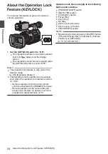
Page 268: ... GY HC550U GY HC550E GY HC500U GY HC500E GY HC500SPCU 4K MEMORY CARD CAMERA RECORDER 2021 JVCKENWOOD Corporation B5A 2966 20 ...

Reviews: