1
Third Gear
Main PCB
Assembly
Feed Motor
Assembly
1
2
2
2
3
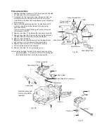
CN502
CN501
Unsolder
Lifter Bracket (L)
Fig. 49
Fig. 50
Tray Motor
Assembly
Unsolder
Traverse
Mechanism
PCB Assembly
Grounding Point
Fig. 51
Pickup Assembly
Shaft Holder
Spindle Motor
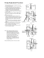
Pickup Replacement Procedure
Note: When replacing the pickup, be sure to
apply countermeasures against static
electricity (grounding the operation table,
wrist band and soldering iron). To remove
it, first short-circuit the grounding point on
the mechanism PCB, then lift the
mechanism PCB assembly with CN501
connected. Next, short-circuit the
grounding point on the pickup main unit,
then unplug the pickup flexible PCB from
connector CN501.
When reassembling, perform in the reverse order.
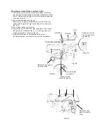
1. Remove the bottom cover, front panel and top cover
from the exterior section.
2. Unplug the flexible ribbon wire from connector CN502
on the traverse mechanism PC board assembly.
3. Turn the rear slider and third gear in the lifter section
counterclockwise until the traverse mechanism
assembly is in the lowermost (bottom) position.
4. Unsolder the two wires (black and brown) connected
to the tray motor.
5. Remove the two screws (1) from the round holes on
the chassis R assembly to remove the lifter bracket
(L).
6. Remove the lower rod.
7. Short-circuit the grounding point on the traverse
mechanism PCB assembly of the lifter unit. Unsolder
the wires connected to the spindle motor (red, black)
and to the feed motor (blue, white) to lift the PCB
assembly.
Next, short-circuit the grounding point on the pickup
main unit and unplug the pickup flexible PCB from
CN501.
8. Remove the three fixing screws (2) from the round
holes on the chassis R assembly to remove the
traverse mechanism PCB assembly.
9. Remove the pickup shaft holder fixing screw (3) to
remove the pickup assembly.
Summary of Contents for CH-X200
Page 1: ......
Page 19: ......
Page 21: ......
Page 22: ......
Page 23: ......
Page 24: ......
Page 25: ......
Page 26: ......
Page 27: ......
Page 29: ......
Page 30: ......
Page 31: ......
Page 32: ......
Page 36: ......
Page 38: ......
Page 39: ......
Page 40: ......
Page 41: ......
Page 42: ......
Page 43: ...Packing Materials and Accessories Parts List Block No M3MM Block No M4MM ...
Page 44: ......
Page 45: ......


