

QFX5110-48S Quick Start Guide
See the complete QFX Series documentation at
http://www.juniper.net/techpubs/ .
To mount, connect power to, and perform the initial configuration of a
Juniper Networks QFX5110-48S, you need:
z
Electrostatic discharge (ESD) grounding strap (not provided)
z
One pair of side-mounting rails (provided)
z
One pair of rear-mounting blades (provided)
z
Twelve screws to secure the mounting rails and mounting blades to the chassis
(provided)
z
Eight screws to secure the chassis and mounting blades to the rack (not provided)
z
Screwdriver appropriate for your rack mounting screws (not provided)
z
Two power cords with plugs appropriate for your geographical location (provided)
z
RJ-45 cable and RJ-45 to DB-9 serial port adapter (provided)
z
Management host, such as a PC laptop, with a serial port (not provided)
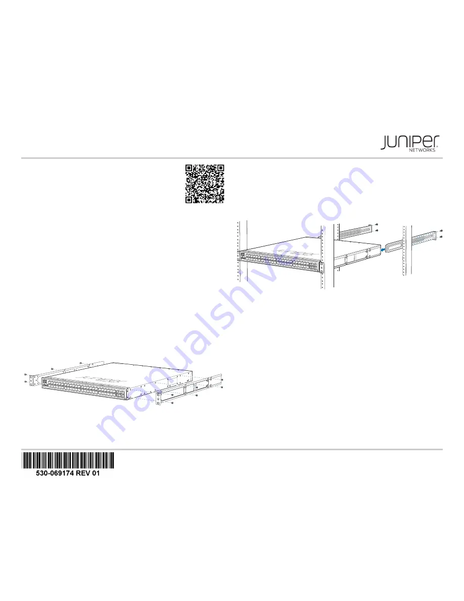
Part 1: Mount the Switch
The QFX5110-48S can only be mounted in a four-post 19 inch rack configuration.
To mount the switch:
1. Attach the ESD grounding strap to your bare wrist and to a site ESD point.
NOTE:
If you are mounting multiple units in the rack, mount the heaviest unit at the
bottom and mount the others from bottom to top in order of decreasing weight. The
switch weighs approximately 23 lb (10.4kg). Installing the QFX5110-48S in a rack or
cabinet requires two persons to lift the switch and secure it to the rack.
2. Place the rack in its permanent location, allowing adequate clearance for airflow and
maintenance, and secure it to the building structure.
3. Determine whether the end with field replaceable units (FRUs) or the ports must be
placed at the front of the rack.
4. Align the holes in the side-mounting rail with the holes on the side of the chassis.
5. Attach the side-mounting rail to the switch using six mounting screws.
6. Repeat Step 4 and Step 5 on the opposite side of the device.
7. Have one person grasp both sides of the switch, lift it, and position it in the rack so
that the front bracket is aligned with the rack holes.
8. Have the second person secure the front of the switch to the rack by using four
mounting screws (and cage nuts and washers if your rack requires them). Tighten the
screws.
9. Continue to support the switch while sliding the rear-mounting blades into the
channel of the side-mounting rails and securing the blades to the rack. Use the four
mounting screws (and cage nuts and washers if your rack requires them) to attach
each blade to the rack. Tighten the screws.
10. Ensure that the switch chassis is level by verifying that all the screws on the front of
the rack are aligned with the screws at the back of the rack
11. Attach a grounding cable to earth ground and then attach it to the chassis grounding
points.
Part 2: Connect Power to the Switch
The switch is supplied with two factory-installed power supplies.
To connect power to an AC-powered switch:
1. If the AC power source outlet has a power switch, set it to the off (0) position.
2. Insert the coupler end of the power cord into the AC power cord inlet on the AC
power supply faceplate.
3. Push the power cord retainer onto the power cord.
4. Insert the power cord plug into the power source outlet.
5. If the AC power source outlet has a power switch, set it to the on (|) position.
6. Verify that the AC and the DC LEDs are lit green and on steadily.
Part 3: Perform the Initial Configuration
You must perform the initial configuration of the switch through the console port. Before
you begin, set the following parameter values in the console server or PC:
z
Baud Rate—9600
z
Flow Control—None
z
Data—8
z
Parity—None
Attach mounting brackets artwork goes here
g050478
GM
g050480
GM


