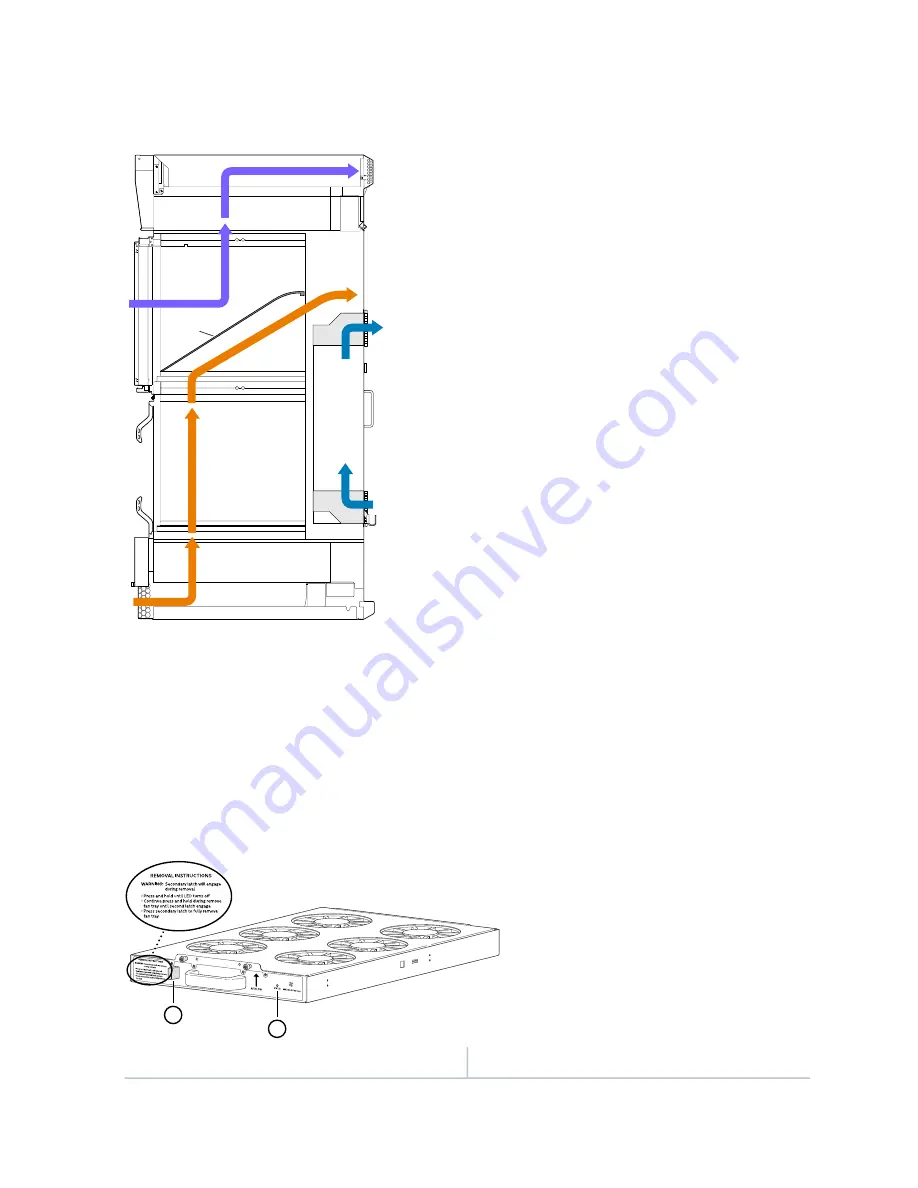
Figure 18: Airflow Through the Chassis
g007408
Lower fan trays
Upper Fan trays
Power
supply
cooling
Card cage
Airflow
divider
Card cage
The MX2010 router provides a two-stage front-to-back cooling system. Air is pushed into the bottom
inlet and up through the lower fan tray, and exits through the opening between the backplanes in the
center of the chassis. This cools the bottom MPCs, and half of each SFB and CB-RE. Air is pulled through
the SFBs and all the CB-REs in the center of the chassis and is exhausted out the upper rear of the system.
The CB-REs and SFBs are equipped with an air divider to deflect the exhaust air for the bottom half of the
system out and direct the air for the top half of the system out.
Figure 19: Upper/Lower Fan Tray
g007035
1
1
2
2
—
1
—
STATUS LED
Safety double latch system
47
Summary of Contents for MX2010
Page 1: ...MX2010 Universal Routing Platform Hardware Guide Published 2019 12 03...
Page 28: ......
Page 30: ...MX2010 Power System Description 95 MX2010 Cooling System Description 45 4...
Page 144: ...MX2010 DC Power 48 V System Electrical Specifications 201 122...
Page 146: ......
Page 233: ......
Page 273: ...Figure 98 Loading the MX2010 Router into the Rack g007436 256...
Page 294: ...Figure 113 Reinstalling an AC Power Distribution Module g007440 D 277...
Page 295: ...Figure 114 Reinstalling a DC Power Distribution Module 48 V D g007432 278...
Page 373: ...4 PART Installing and Replacing Components Installing Components 359 Replacing Components 429...
Page 374: ......
Page 620: ......
Page 715: ...6 PART Troubleshooting Hardware Troubleshooting Components 703...
Page 716: ......
Page 744: ......
Page 772: ......
Page 775: ...763...
Page 783: ...772...
Page 796: ...Jewelry Removal Warning 787...
Page 799: ...Operating Temperature Warning 790...
Page 808: ...DC Power Disconnection Warning 799...
Page 812: ...DC Power Wiring Sequence Warning 803...


