


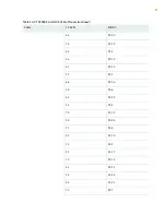

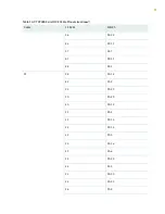


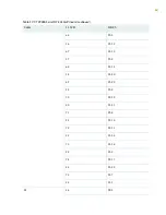
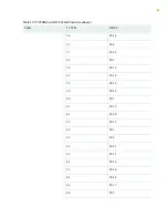

Table 11: CTP2000 4WE&M RTM Pinouts–Connector A (continued)
Connector A
Pin
Signal
Signal
Pin
27
Port 0 T1
Port 0 R1
2
28
Port 0 E
Port 0 SG
3
29
Port 0 M
Port 0 SB
4
30
Port 1 T
Port 1 R
5
31
Port 1 T1
Port 2 R1
6
32
Port 1 E
Port 2 SG
7
33
Port 1 M
Port 2 SB
8
34
Port 2 T
Port 2 R
9
35
Port 2 T1
Port 2 R1
10
36
Port 2 E
Port 2 SG
11
37
Port 2M
Port 2 SB
12
38
Port 3 T
Port 3 R
13
39
Port 3 T1
Port 3 R1
14
40
Port 3 E
Port 3 SG
15
41
Port 3 M
Port 3 SB
16
50
GND
GND
25
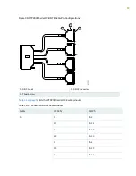
CTP2000 4WE&M Connector B Pinouts
See
for connector B pinout information. See
“CTP2000 4WE&M Interface Module”
for signal definitions.
46
Summary of Contents for CTP2000 Series
Page 1: ...CTP2000 Series Circuit to Packet Platforms Hardware Guide Published 2020 08 31 ...
Page 8: ...1 PART Overview CTP2000 Series Platform Overview 2 CTP2000 Series Interface Modules 11 ...
Page 112: ...Installing SFPs in a CTP2000 Module 102 105 ...
Page 127: ...5 PART Configuration Accessing the CTP2000 Platform 121 ...
Page 144: ...7 PART Troubleshooting Troubleshooting Power Failures 138 Contacting Customer Support 140 ...


