background image

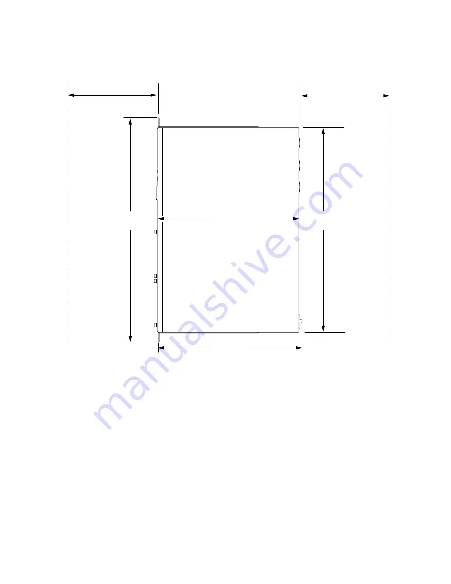
Figure 8: Clearance Requirements for Airflow and Hardware Maintenance for a CTP151 Device

g100907

Front

(Ports)

Rear

19.0 in.

(48.26 cm)

17.36 in.

(44.08 cm)

12.0 in.

(30.51 cm)

12.19 in.

(30.95 cm)

Clearance required

for maintenance

24 in. (61 cm)

Clearance required

for maintenance

24 in. (61 cm)

For the cooling system to function properly, the airflow around the chassis must be unrestricted. See

“CTP151 Cooling System” on page 7

for more information about the airflow through the chassis.

If you are mounting a CTP151 device in a rack or cabinet with other equipment, ensure that the exhaust

from other equipment does not blow into the intake vents of the chassis.

Leave at least 24 in. (61 cm) both in front of and behind the CTP151 device. For service personnel to

remove and install hardware components, you must leave adequate space at the front and back of the

CTP151 device. NEBS GR-63 recommends that you allow at least 30 in. (76.2 cm) in front of the rack

or cabinet and 24 in. (61 cm) behind the rack or cabinet.

RELATED DOCUMENTATION

22

Summary of Contents for CTP151 Platform

Page 1: ...Juniper Networks CTP151 Circuit to Packet Platform Hardware Guide Published 2020 02 07...

Page 2: ...s the right to change modify transfer or otherwise revise this publication without notice Juniper Networks CTP151 Circuit to Packet Platform Hardware Guide Revision History February 2020 Revision 1 Th...

Page 3: ...of CTP151 Platform 5 Chassis Status LEDs 5 CTP151 Cooling System 7 Power Supply in the CTP151 Device 8 CTP151 Interface Modules 9 CTP151 Serial Interface Module 9 CTP151 Multiservice Interface Module...

Page 4: ...rt Adapter Pinout Information for a CTP151 Device 32 CTP151 Interface Module HD 26 Connector Cable Pinouts 33 EIA 530 Connector Interface Signal Pinouts DB 25 Female DCE 34 EIA 530 Connector Interface...

Page 5: ...nterface Module Processor Module or Clock Module 61 Cabling 65 Connecting a CTP151 Device to a Network for Out of Band Management 65 Connecting a CTP151 Device to a Management Console 66 Connecting a...

Page 6: ...Returning a CTP151 Device or Component for Repair or Replacement 89 Locating the Chassis Serial Number ID Label on a CTP151 Device 90 Contacting Customer Support to Obtain a Return Materials Authoriza...

Page 7: ...at https www juniper net documentation If the information in the latest release notes differs from the information in the documentation follow the product Release Notes Juniper Networks Books publishe...

Page 8: ...text and syntax conventions used in this guide Table 2 Text and Syntax Conventions Examples Description Convention To enter configuration mode type the configure command user host configure Represent...

Page 9: ...b default metric metric Encloses optional keywords or variables angle brackets broadcast multicast string1 string2 string3 Indicates a choice between the mutually exclusive keywords or variables on ei...

Page 10: ...stem Click TechLibrary Feedback on the lower right of any page on the Juniper Networks TechLibrary site and do one of the following Click the thumbs up icon if the information on the page was helpful...

Page 11: ...niper net Find product documentation https www juniper net documentation Find solutions and answer questions using our Knowledge Base https kb juniper net Download the latest versions of software and...

Page 12: ...1 PART Overview CTP151 Platform Overview 3 CTP151 Interface Modules 9...

Page 13: ......

Page 14: ...t chassis high port density and multiple Ethernet interfaces Each CTP Series platform runs the CTP operating system CTPOS and can be managed by the Juniper Networks CTPView Network Management System T...

Page 15: ...front panel components of a CTP151 Figure 1 Front Panel Components of a CTP151 g100902 1 2 3 4 6 9 8 7 5 6 1 Interface module slots Mini USB console port 7 2 Two 1 Gigabit Ethernet 10 Gigabit Ethernet...

Page 16: ...ounding points 4 Serial number RELATED DOCUMENTATION Introducing CTP Series Platforms 3 LED Details of CTP151 Platform 5 CTP151 Serial Interface Module 9 CTP151 T1 E1 Interface Module 12 LED Details o...

Page 17: ...mode command show chassis led Table 3 Chassis Status LEDs in a CTP151 Description Color State LED Label The device is powered off or is halted Off SYS System The device is running but the ctpd proces...

Page 18: ...assis is located on the front of the chassis Air is pulled into the chassis and pushed toward the fans which are built in Hot air exhausts from the rear of the chassis See Figure 4 on page 7 Figure 4...

Page 19: ...ge Operating Range Internal 150 W 1 8 A maximum 50 60 Hz nominal 100 240 VAC A detachable AC power cord is supplied with the AC power supplies The coupler is type C13 as described by International Ele...

Page 20: ...also has the option of supporting two multiservice daughter cards for 4 KHz or high quality analog audio or interrange instrumentation group IRIG signals See CTP151 Multiservice Interface Module on pa...

Page 21: ...2 kHz reference output and configure an external clock reference the module expects an RS 422 clock input of the configured frequency on the same pins RELATED DOCUMENTATION CTP151 Multiservice Interfa...

Page 22: ...options for 64Khz 4WTO analog high quality analog or IRIG The module also includes an external clock reference port CLK for an HD 26 connector Note that only one external clock reference is required e...

Page 23: ...st numbered port labeled 3 is on the left and the lowest numbered port labeled 0 is at the right with the CLK port still farther to the right Figure 7 CTP151 T1 E1 Interface Module g100917 1 2 3 3 1 S...

Page 24: ...RELATED DOCUMENTATION CTP151 Serial Interface Module 9 CTP151 Multiservice Interface Module 10 CTP151 Interface Module HD 26 Connector Cable Pinouts 33 13...

Page 25: ...2 PART Planning System Specifications 17 Planning and Preparing the Site 19 Cable and Pinout Specifications 27...

Page 26: ......

Page 27: ...atform Chassis Physical Specifications Table 5 CTP151 Platform Chassis Physical Specifications Specification Category 9 9 lb 4 49 kg Weight 1 73 in 4 4 cm Height 17 36 in 44 1 cm Width 12 in 30 5 cm D...

Page 28: ...ng environment for your device and prevent environmentally caused equipment failures Keep the area around the chassis free from dust and conductive material such as metal flakes Follow prescribed airf...

Page 29: ...evice Table 6 CTP151 Device Environmental Tolerances Tolerance Description No performance degradation up to 2000 meters at 96 F 40 C Altitude Normal operation ensured in relative humidity range of 5 t...

Page 30: ...recommended distances use a high quality twisted pair cable with one ground conductor for each data signal when applicable Radio frequency interference If your site is susceptible to problems with ele...

Page 31: ...e 7 for more information about the airflow through the chassis If you are mounting a CTP151 device in a rack or cabinet with other equipment ensure that the exhaust from other equipment does not blow...

Page 32: ...ount the device on any two post or four post rack that provides bracket holes or hole patterns spaced at 1 U 1 75 in or 4 45 cm increments and that meets the size and strength requirements to support...

Page 33: ...d rack Rack size and strength Secure the rack to the building structure If earthquakes are a possibility in your geographical area secure the rack to the floor Secure the rack to the ceiling brackets...

Page 34: ...assist with removing the hot air exhaust Install the CTP151 device in the cabinet in a way that maximizes the open space on the side of the chassis that has the hot air exhaust Route and dress all cab...

Page 35: ...tion or airflow Route cables so that modules and field replaceable units are easily accessible Route cables in a logical direction to prevent loss of connectivity to other equipment in the rack associ...

Page 36: ...Module HD 26 Connector Cable Pinouts 33 Cable Specifications for Console Connections for the CTP151 Device Table 10 on page 27 lists the specifications for the cables that connect the CTP151 device t...

Page 37: ...he device through this port in the debugger prompt The Mini USB console port uses a Mini B plug 5 pin connector to connect to a console management device The default baud rate for the console port is...

Page 38: ...le port on the front panel of the CTP151 to connect your laptop or PC directly to the CTP151 device If your PC or laptop has a DB 9 male connector pin you can use a combination of the RJ 45 cable and...

Page 39: ...ble behavior Juniper Networks Technical Assistance Center JTAC can provide only limited support for issues related to unsupported hardware We strongly recommend that you use only supported USB flash d...

Page 40: ...Transmit receive data pair 3 TRP3 4 Transmit receive data pair 3 TRP3 5 Transmit receive data pair 2 TRP2 6 Transmit receive data pair 4 TRP4 7 Transmit receive data pair 4 TRP4 8 RELATED DOCUMENTATI...

Page 41: ...51 Platform Overview 3 RJ 45 to DB 9 Serial Port Adapter Pinout Information for a CTP151 Device The console port is an RS 232 serial interface that uses an RJ 45 connector to connect to a management d...

Page 42: ...Device to a Management Console 66 CTP151 Interface Module HD 26 Connector Cable Pinouts IN THIS SECTION EIA 530 Connector Interface Signal Pinouts DB 25 Female DCE 34 EIA 530 Connector Interface Signa...

Page 43: ...IA 530 Connector Interface Signal Pinouts DB 25 Female DCE Table 16 on page 34 lists the EIA 530 interface signal pinouts for the HD 26 connector to the female DB 25 connector for the CTP151 platform...

Page 44: ...output from CTP 10 19 CC Data set ready DSR B output from CTP 22 20 RL Remote loopback RL input to CTP 21 21 TM Test mode TM output from CTP 25 22 Ground Signal ground GND 7 24 26 CD Data terminal re...

Page 45: ...lear to send B input to CTP 13 10 Clear to send A input to CTP 5 11 Data set ready A input to CTP 6 12 Local loopback output from CTP 18 13 Transmit Data B output from CTP 14 14 Transmit Clock from DT...

Page 46: ...CTP 2 5 Signal Out A output from CTP 5 8 Signal Out B output from CTP 12 9 Signal In B input to CTP 10 10 Signal In A input to CTP 3 11 Receive Data B output from CTP 11 14 Receive Clock B output fro...

Page 47: ...10 Signal In A input to CTP 3 11 Transmit Data B output from CTP 11 14 Transmit Clock B output from CTP 13 15 Receive Clock B input to CTP 14 17 Receive Data B input to CTP 9 18 Ground 8 24 26 V 24 C...

Page 48: ...gnal Pinouts RJ 45 Male Table 21 on page 39 lists the T1 E1 interface module pinout for the RJ 45 connector Table 21 T1 E1 Interface Module RJ 45 Connector Pinout Signal RJ 45 Pin RX Ring 1 RX Tip 2 3...

Page 49: ...3 PART Safety General Safety Guidelines and Warnings 43 Module Installation Safety Guidelines and Warnings 45 Hardware Compliance and Homologation 47...

Page 50: ......

Page 51: ...nstall equipment in the rack from the bottom upward Doing this helps maintain the stability of the rack and reduces the chance of the rack tipping over WARNING Do not insert any metal object such as a...

Page 52: ...emove jewelry including rings necklaces and watches before working on equipment that is connected to power lines Metal objects heat up when connected to power and ground and can cause serious burns or...

Page 53: ...fore attaching power cables WARNING Remove jewelry including rings necklaces and watches before working on equipment that is connected to power lines Metal objects heat up when connected to power and...

Page 54: ...RELATED DOCUMENTATION Required Tools and Safety Items for Installing CTP Modules 58 Installing a CTP Interface Module Processor Module or Clock Module 59 46...

Page 55: ...mpatibility EMC EN 300 386 Telecom Network Equipment EMC requirements EN 55032 CISPR 32 Class A Electromagnetic compatibility of multimedia equipment Emission requirements EN 55022 CISPR 22 Informatio...

Page 56: ...TEC SD DD EMC 221 05 OCT 16 India EMC standard IEC EN 61000 Immunity requirements RELATED DOCUMENTATION CTP151 Platform Overview 3 CTP151 Safety Guidelines and Warnings 43 48...

Page 57: ...4 PART Installation Unpacking and Mounting the CTP151 Device 51 Installing Modules 57 Cabling 65...

Page 58: ......

Page 59: ...compartment and contains the quick start instructions CAUTION CTP151 device is maximally protected inside the shipping carton Do not unpack the devices until you are ready to begin installation To unp...

Page 60: ...es without toll free numbers see https www juniper net support requesting support html Table 22 on page 52 lists the parts and their quantities in the packing list Table 22 Packing List for a CTP151 D...

Page 61: ...tion base is moved Juniper Networks will not be held accountable for not meeting the hardware replacement service level agreement for products that do not have registered serial numbers or accurate in...

Page 62: ...device to the rack CAUTION If you are mounting multiple devices on a rack mount a device in the bottom of the rack first and proceed to mount the rest of the devices from bottom to top To mount the de...

Page 63: ...of the device lift the device and position it in the rack aligning the mounting bracket holes with the threaded holes in the rack or cabinet rail Align the bottom hole in both the mounting brackets wi...

Page 64: ...screws Tighten the screws 8 Ensure that the device chassis is level by verifying that all screws on one side of the rack are aligned with the screws on the other side RELATED DOCUMENTATION Rack Requi...

Page 65: ...ing is from left to right 0 to 1 Any single module must be installed in slot 0 and any single clock connection must come from the port in slot 0 CTP151 port numbering on the front panel for the serial...

Page 66: ...iller panel to protect the device from dust or other foreign substances and to ensure proper device cooling CAUTION Do not discard the antistatic bag When a module is not in use store it in an antista...

Page 67: ...t 0 3 With a Phillips screwdriver loosen the screws that secure the blank filler panel covering the empty chassis slot if present and remove the filler panel 4 Remove the module from its antistatic ba...

Page 68: ...cent module so that proper electromagnetic interference EMI gasket compression occurs Failure to do this can make it difficult to install adjacent modules RELATED DOCUMENTATION Removing a CTP Interfac...

Page 69: ...3 Wrap and fasten one end of the ESD grounding strap around your wrist and connect the other end to a site ESD point 4 Use a Phillips screwdriver to loosen the captive screws located at the upper rig...

Page 70: ...onents pins leads or solder connections 8 Cover the empty chassis slot with a blank filler panel and tighten the filler panel s captive screws using a Phillips screwdriver Turn both screws several tim...

Page 71: ...CTP151 Platform Overview 3 63...

Page 72: ...dedicated management channel The CTP151 device has four 10 100 1000BASE T RJ 45 ports two SFP ports one management port one RJ 45 console port one Mini USB console port and one USB 3 0 port Use the ma...

Page 73: ...h an RJ 45 connector Use the console port to connect the device to a management console or to a console server Before you begin ensure that you have a rollover cable available To connect the CTP151 de...

Page 74: ...d manage the CTP151 device by using the RJ 45 console port or the Mini USB Type B console port The console input will be active only on one port at a time By default the RJ 45 port is set as the activ...

Page 75: ...connector of the Mini USB cable to the host machine PC or laptop 2 Connect the Mini USB Type B 5 pin connector of the Mini USB cable to the Mini USB Type B console port labeled CON on the CTP151 devic...

Page 76: ...ace module push the serial HD 26 cable into the module and tighten the thumb screws 3 Gently pull the cable to confirm that it is inserted correctly For more information about CTP151 cable and pinout...

Page 77: ...5 PART Configuration Accessing the CTP151 Platform 73 Powering On and Initially Configuring the CTP151 Device 75...

Page 78: ......

Page 79: ...sole Before you begin connecting a CTP151 device to a console management device you must ensure that the HyperTerminal properties of the serial port on the console management device are set as follows...

Page 80: ...address on the front panel of the CTP151 chassis 2 Connect the other end of the cable to the appropriate Ethernet network for an out of band connection CAUTION Do not change the IP address for the Et...

Page 81: ...d to a power source For specifications on the electrical requirements for the device see CTP151 Platform Chassis Physical Specifications on page 17 CAUTION Evaluate the overall loading of the branch c...

Page 82: ...d the CTPOS software on the internal SSD To bring up the CTP151 device with CTPOS on the internal SSD using a USB storage device 1 Download and copy the CTPOS software USB installation image to a USB...

Page 83: ...ctp and the default password for the ctp_cmd user account is ctp_cmd You can change the default passwords later Supported protocol or protocols 0 IPv4 only 1 IPv6 only or 2 IPv4 and IPv6 Enter the app...

Page 84: ...IPv6 Only 2 IPv4 IPv6 Please select your option rtn for 0 There are 2 ethernet devices available for use The default device is the device through which the default gateway can be accessed Ctp circuit...

Page 85: ...storage Backing up usr local to nonvolatile storage Setting up date time Setting the date GMT Please input the year 2008 2020 return for 2010 Setting the date GMT Please input the month 1 12 return fo...

Page 86: ...elect 5 Node Operations 3 From the Node Operations Menu select 10 Powerdown Node 4 Monitor the console output during shutdown and look for the following message reboot Power down 5 Turn off the power...

Page 87: ...6 PART Maintenance Maintaining Components 83 Product Reclamation and Recycling 87 Contacting Customer Support and Returning the Chassis or Components 89...

Page 88: ......

Page 89: ...adjustable wrench Antistatic wrist strap Antistatic bags or other protective packaging to hold components Plastic boots or other protective covers for fiber optic connectors RELATED DOCUMENTATION Sto...

Page 90: ...aintaining the CTP151 Device 83 Cleaning the CTP151 Platform 84 Cleaning the CTP151 Platform Dust is attracted to the area where the air intake vents are located Clean the area with a dry cloth every...

Page 91: ...the chassis Before removing the device from a rack Ensure that the rack or cabinet is stable and secured to the building Ensure that there is enough space to place the removed device in its new locati...

Page 92: ...will need them when you reinstall the chassis 3 Lift the chassis from the rack and carefully move the chassis to its new location RELATED DOCUMENTATION CTP151 Safety Guidelines and Warnings 43 Mounti...

Page 93: ...mechanisms for the recycling and reuse of their products The RoHS Directive restricts the use of certain substances that are commonly found in electronic products today Restricted substances include h...

Page 94: ...cled recovered or disposed of in a responsible manner Our packaging is designed to be recycled and should be handled in accordance with your local recycling policies RELATED DOCUMENTATION Returning a...

Page 95: ...Determine the serial number of the device or component For instructions see Locating the Chassis Serial Number ID Label on a CTP151 Device on page 90 2 Obtain a Return Materials Authorization RMA num...

Page 96: ...Authorization RMA from the Juniper Networks Technical Assistance Center JTAC After locating the serial number of the device or component you want to return open a service request with Juniper Network...

Page 97: ...evice or Component for Shipping 91 Packing a CTP151 Device or Component for Shipping If you are returning a CTP151 device or component to Juniper Networks for repair or replacement pack the item as de...

Page 98: ...ce 8 If you are returning accessories or FRUs with the device pack them as instructed in Packing a CTP151 Device or Component for Shipping on page 91 9 Replace the accessory box on top of the packing...

Page 99: ...g tape Write the RMA number on the exterior of the box to ensure proper tracking RELATED DOCUMENTATION Returning a CTP151 Device or Component for Repair or Replacement 89 Contacting Customer Support t...

Page 100: ...7 PART Troubleshooting Troubleshooting Hardware and Power Failures 97...

Page 101: ......

Page 102: ...t normal operation LEDs are the alarm indicators on the device Alarm Seriousness of the alarm The level of severity can be either major red or minor yellow Minor yellow or amber Indicates a noncritica...

Page 103: ...view 3 LED Details of CTP151 Platform 5 CTP151 Platform Does Not Power On Problem Description Symptoms Device is not receiving power Module s power supply has malfunctioned Power source cannot handle...

Page 104: ...ost Solution 1 Verify that power connections are properly attached 2 Verify that device is receiving power 3 Look to see whether or not the LEDs are lit 4 Run diagnostics using the CLI 5 If the device...

Reviews: